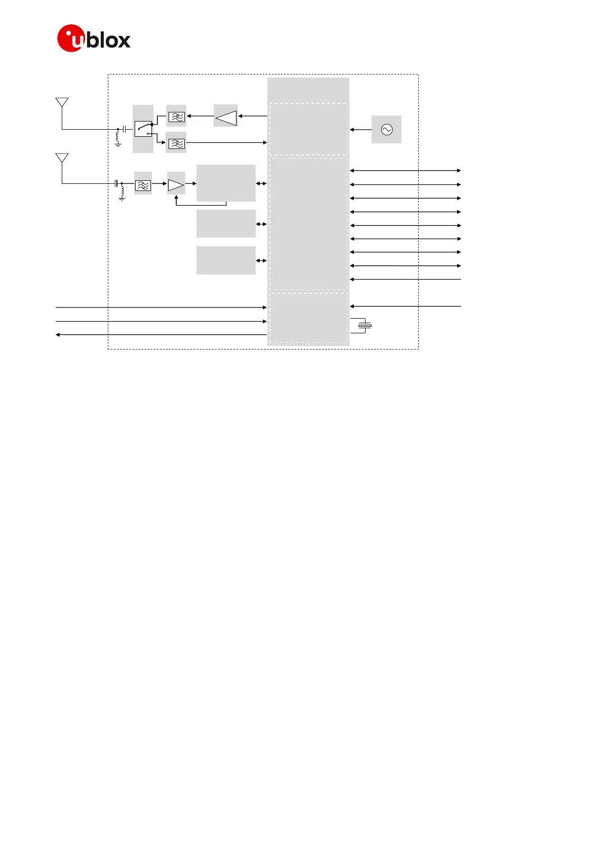
Figure 3: SARA-R510M8S block diagram
☞ The “00” product version of the SARA-R5 series modules do not support the following interfaces,
which should be left unconnected and should not be driven by external devices:
o SPI interface
o SDIO interface
o Digital audio (I2S) interface
SARA-R5 series modules internally consist of the following sections described herein with more
details than the simplified block diagrams of Figure 1, Figure 2 and Figure 3.
RF section
The RF section is composed of the following main elements:
• RF switch connecting the antenna port (ANT) to the suitable RF Tx / Rx paths for LTE Cat M1 / NB2
Half-Duplex operations
• Power Amplifiers (PA) amplifying the Tx signal modulated and pre-amplified by the RF transceiver
• RF filters along the Tx and Rx signal paths providing RF filtering
• RF transceiver integrated in the u-blox UBX-R5 cellular chipset, performing modulation,
up-conversion and pre-amplification of the baseband signals for LTE transmission, and
performing down-conversion and demodulation of the RF signal for LTE reception
• 26 MHz Temperature-Controlled Crystal Oscillator (TCXO) generating the reference clock signal
for the cellular RF transceiver, the Base-Band system and the GNSS system, when the related
system is in active mode or connected mode.

 Loading...


