EVK-R5 - User guide
UBX-19042592 - R06 Starting up Page 6 of 23
C1-Public
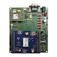
The lower board (EVB-WL3) is also designed to be used with other u-blox cellular adapter boards. It
contains additional switches, jumpers, connectors, LEDs and parts that may be only partially
described in Figure 1 or in this document, because they are intended for use only with other u-blox
cellular modules. It is recommended to leave any additional connector unconnected and any additional
switch in its default configuration.
1.3 Switches, jumpers and buttons
Power on / off of the whole evaluation kit
Jumper socket to provide the 3.8 V supply to the cellular module VCC input
Push button to switch on / off the cellular module
Push button to reset the cellular module
Slide switch to attach / detach the cellular module single UART from the
USB / RS232 connectors on EVB-WL3
Slide switch to select cellular module single UART routing on the USB or
RS232 connector on EVB-WL3
Slide switch to attach / detach the cellular module GPIOs from peripherals:
when detached, the signals are available only on the DIL B2B connector on the
ADP board
Slide switch to attach / detach the cellular module to / from the GNSS module
(GPIO2-3-4): when detached, the signals are available only on the DIL B2B
connector on the ADP board
Slide switch to connect / disconnect backup battery to / from the V_BCKP pin
of the GNSS module
Table 1: EVK-R5 switch and button descriptions
For EVK-R510M8S it is recommended to keep this switch in “detach” position.

 Loading...