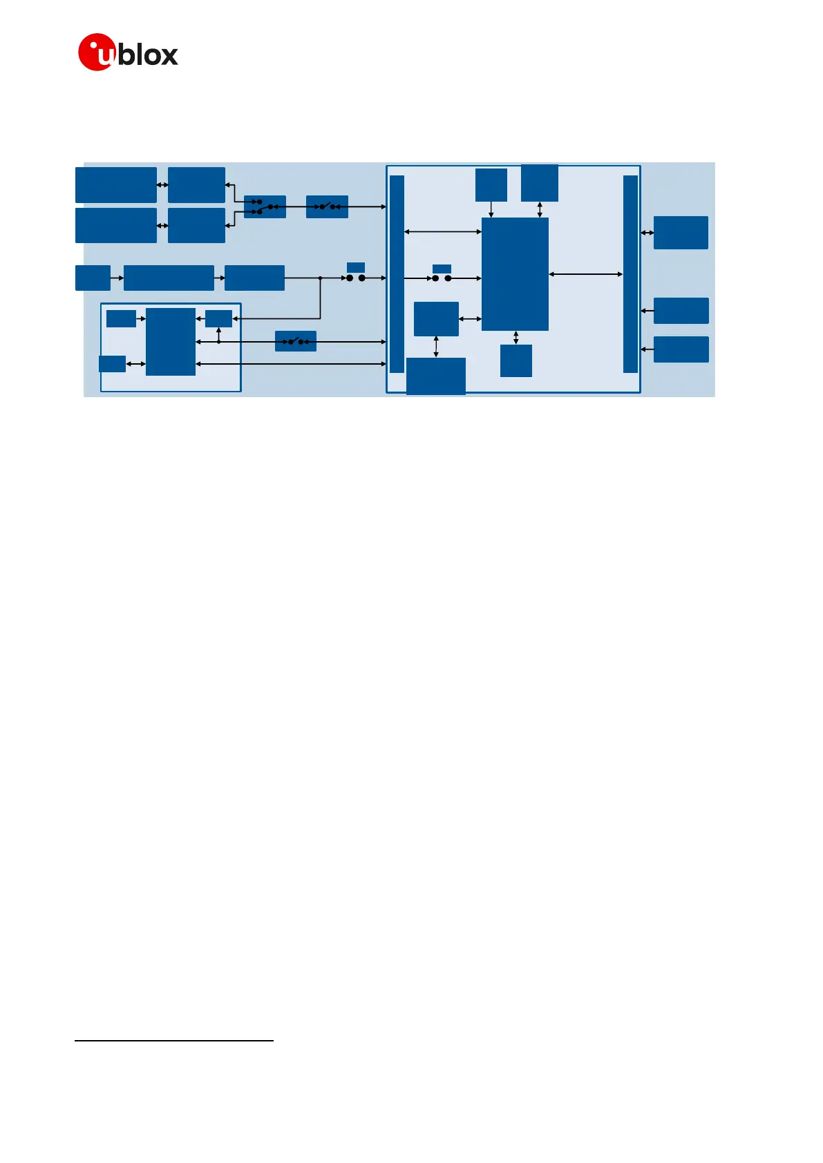
Figure 2: Block diagram of the EVK-R5 for SARA-R5 modules
The EVK-R5 evaluation kit is formed by three boards:
1. The lower one, called EVB-WL3, contains the power supply and other peripherals for the u-blox
SARA-R5 series cellular module (such as SIM card holder, reset button and power-on button).
2. The cellular adapter board, called ADP-R5, contains the u-blox SARA-R5 cellular module, antenna
connectors for the cellular RF interface and the GNSS RF interface
of the SARA-R5 module, USB
connectors for the two UART interfaces and the USB interface of the SARA-R5 module, and the
DIL header connectors (J300 and J301) making the interfaces of the SARA-R5 module
accessible.
3. The GNSS adapter board, called ADP-GNSS, contains the u-blox GNSS module, the GNSS
antenna connector and the USB connector for the GNSS module.
The cellular and the GNSS adapter boards are connected by means of male header board-to-board
connectors provided on the bottom of the adapter boards and their corresponding female connectors
provided on top of the lower board, called EVB-WL3.
If the on-board / B2B switch (SW401) is set to “on-board”, then the single UART interface (with the
default USIO variant 0 setting, or the USIO variant 1 setting) is available on DIL connectors on the
cellular adapter board. It is routed up to the RS232 DB9 connector (J500) or the USB connector (J501)
mounted on the EVB-WL3 board according to the settings of the mini-USB / DB9 switch (SW403).
If the on-board / B2B switch (SW401) is set to “B2B”, then the two UART interfaces (with the +USIO
variant 2, 3 or 4 setting) are available on the USB connector (J201) mounted on the cellular adapter
board.
The USB interface of the cellular module (available for diagnostic purpose only) is available on the
native USB connector (J105) mounted on the cellular adapter board.
Other SARA-R5 series peripherals are available on the dual-in-line male board-to-board connectors
provided on the top layer of the cellular adapter board (J300 and J301), which are pin-to-pin
compatible with the connectors on the bottom layer of the adapter board.

 Loading...


