Installations- och driftinstruktion Installation and Operation Manual
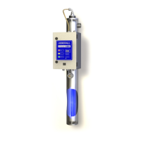
UV-system typ UBK UV sterilizer series UBK
© UEBERALL 2007
Sida / Page 4 / 13
Installation av UV-system
Installation of UV sterilizer
Varning:
Utrustningen levereras driftklar med installerade
kvartsglas och UV-lampa. Den får inte utsättas för
slag eller stötar. Låt den inte välta och tappa den
inte!
Caution:
Unit will be delivered operational with quartz jacket and
UV-lamp already installed. Do not shock, let it not tip or
fall over!
Att beakta vid installation:
1. Utrustningen skall installeras vertikalt.
2. Ovanför utrustningen måste det finnas plats
för byte av UV-lampa. Se måttuppgift på
aktuell måttritning.
3. Vid behov, montera UV-reaktorn på vägg
med rostfria klammer för väggmontage eller
rörklammer med gummiinlägg.
4. Montera avstängningsventiler på
anslutningar för inlopp och utlopp.
5. Vid behov, montera magnetventil och/eller
flödesbegränsare som visas på ritningen.
6. Avlufta UV-reaktorn helt vid vattenfyllning.
7. Efter installation och vattenfyllning skall
systemet tryckprovas med högsta tillåtna
drifttryck.
8. Utsätt aldrig utrustningen för högre tryck än
högsta tillåtna drifttryck. Undvik tryckslag.
9. Elektrisk anslutning skall göras enligt bifogat
kopplingsschema.
10. För externt larm finns utgångar från en
växlande kontakt.
Flödesbegränsare för UBK-1
inställd till max. 4 m³/h
Flödesbegränsare för UBK-2
inställd till max. 6 m³/h
Flödesbegränsare för UBK-3
inställd till max. 9 m³/h
Flödesbegränsare för UBK-4
inställd till max. 16 m³/h
Please observe:
1. Unit for vertical installation only.
2. Necessary service height over the unit for UV-lamp
replacement must be observed as shown on the
related Dimension Drawings.
3. If necessary mount the UV-radiation chamber on
two wall mounting clamps of stainless steel or within
rubber inserts as shown on the drawing.
4. Provide gate valves for inlet and outlet.
5. If any, locate the solenoid valve and the flow control
valve as shown on the drawing.
6. Completely deaerate the UV-radiation chamber
while filling.
7. After installation and filling up a pressure test
should be executed. Nominal pressure is maximum
pressure allowed.
8. Do not exceed nominal pressure in operation! Avoid
pressure shocks.
9. Execute electrical connection according to wiring
diagram.
10. For the outgoing alarm a break and a make contact
is provided.
Flow Control Valve for UBK-1
set to max. 4 m³/h
Flow Control Valve for UBK-2
set to max. 6 m³/h
Flow Control Valve for UBK-3
set to max. 9 m³/h
Flow Control Valve for UBK-4
set to max. 16 m³/h