VLS Service Manual - REV2015.04
Table of Contents
Adjustments and Settings
Page | 17
Adjustments
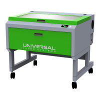
6. Locate the Y-axis couplers (1). On both couplers there are two screws that mount the coupler to the
Y-motor and the Y-axis shaft. Using a 3/32 inch Allen wrench, choose only ONE of those screws (2) and
loosen it ½ turn.
7. Grasp the center of the X-axis arm and pull it forward to contact the shoulder screws. While holding the
arm against the two shoulder screws, tighten the screw loosened in the previous step.
8. Push the arm into the approximate center of the engraving field. With your left thumb and forefinger,
touch the two Y-axis bearings and attempt to turn or rotate them.
NOTE: You should feel an equal turning resistance for each bearing. If one bearing spins freely and the other
has a turning resistance, or the turning resistance is unequal, then adjustment is necessary.
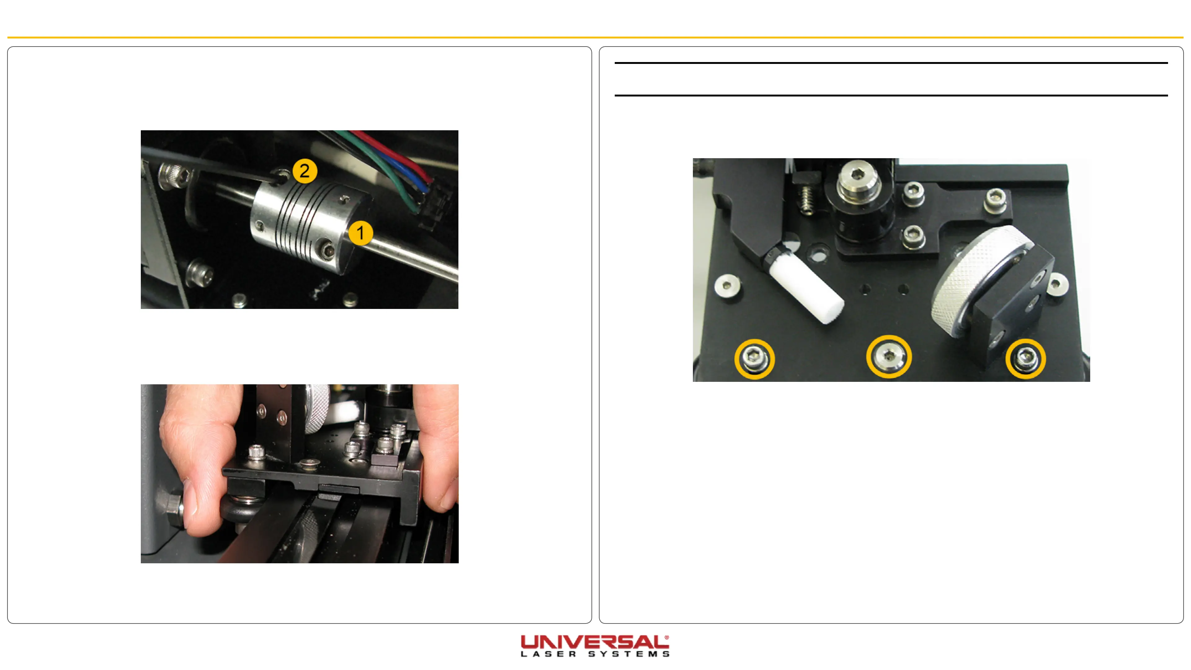
9. Using an Allen wrench, loosen the three highlighted screws ¼ turn. Then, re-tighten them. This
procedure automatically equalizes the force on both Y-axis bearings. Re-check the turning resistance
once again and re-adjust if necessary.
10. Re-install the #2 mirror cover.
Adjustments and Settings
 Loading...