VLS Service Manual - REV2015.04
Table of Contents
Component Removal and Replacement
Page | 28
Component Removal and Replacement
NOTE: DO NOT remove the screws behind the mirror. This assembly is spring loaded.
5. Replace the #2 Mirror with the new mirror. Verify that the reflection side is facing inside the laser
machine. Installing the mirror backward within the bezel will destroy the mirror once the laser beam
penetrates the backside of the mirror, so be sure that you re-install the mirror correctly.
6. Once the mirror has been installed perform a Laser Beam Check and Alignment.
Replace Mirror #2
NOTE: Be careful not to touch the #2 Mirror.
1. Make sure the VLS is powered OFF and unplugged.
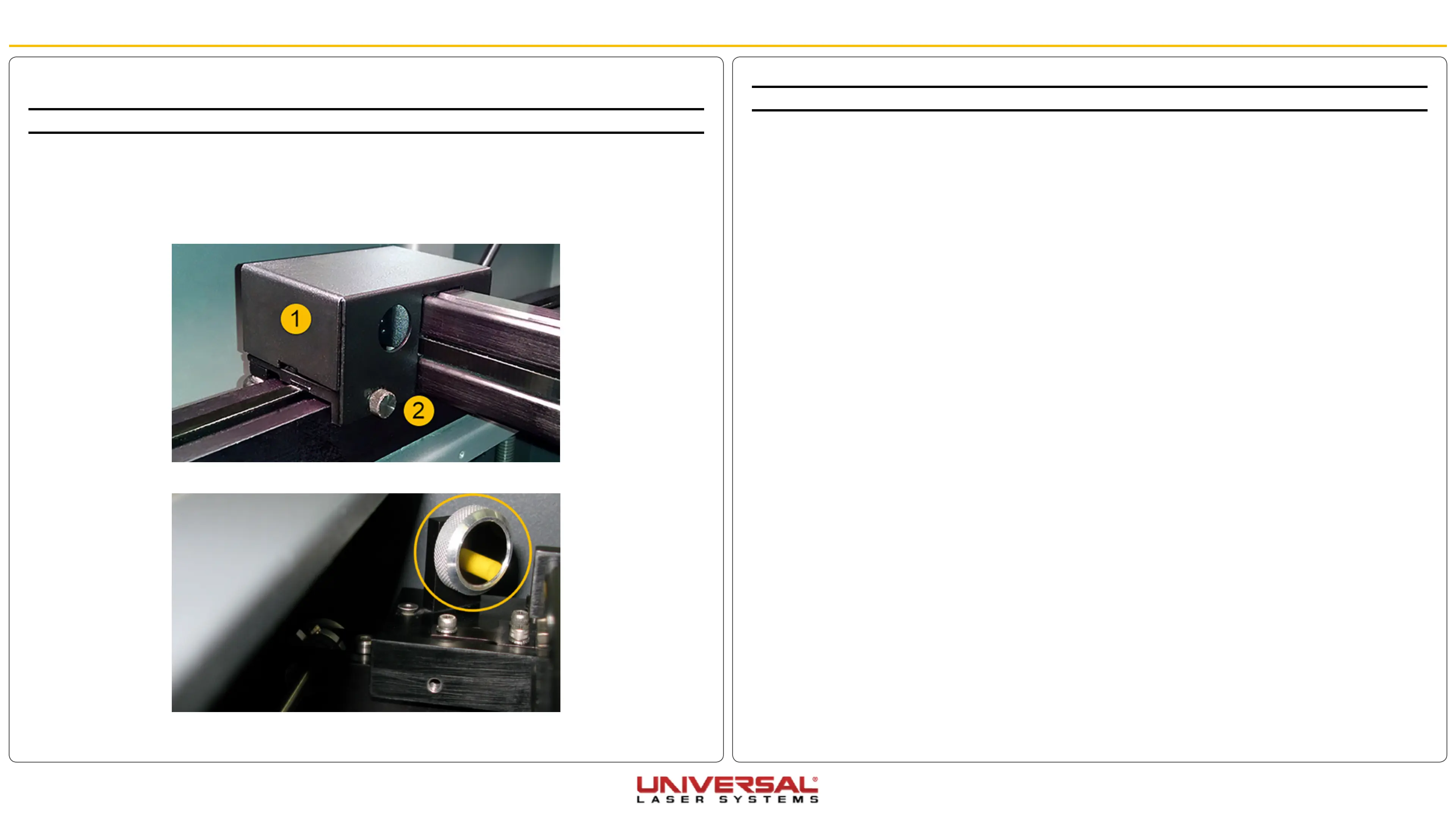
2. Open the Top Door and slide the X-axis Arm forward.
3. Locate and carefully remove the large thumb screw (2) securing the cover (1) on the left-hand side of
the X-axis arm. Once the thumbscrew is removed slide the cover to the right and up and set it aside.
4. Grab hold of the Bezel Mirror Holder and turn it counter-clockwise to remove it. Place it in a safe place.