VLS Service Manual - REV2015.04
Table of Contents
Component Removal and Replacement
Page | 41
Component Removal and Replacement
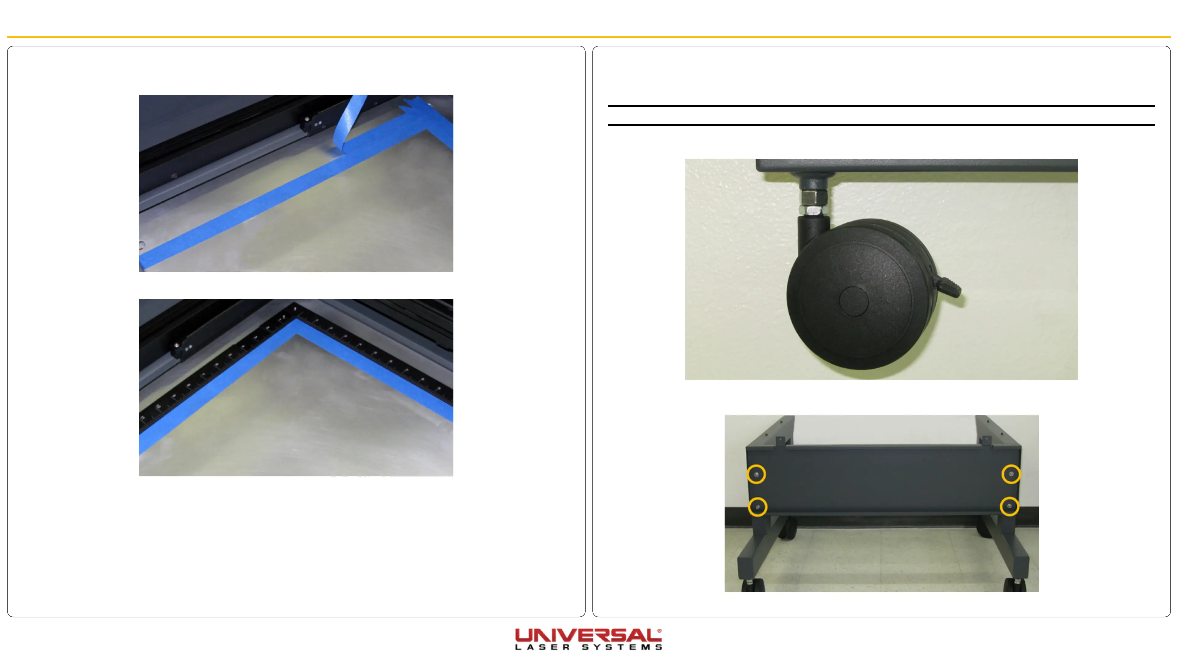
Cart
VLS3.60 and VLS4.60
NOTE: Leave all the screws slightly loose except for the casters.
1. Screw the 4 casters onto each leg, 2 per leg, as far as possible.
2. Attach the back panel to the legs using the 4 socket head screws, 4 locking washers, and 4 flat
washers.
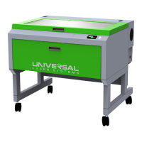
6. After the cut file has been run, peel the outside masking layer off leaving the inside portion. This will be
the guideline to set the rulers.
7. Gently set the rulers against the remaining masking tape.
8. Once the rulers are correctly located, reinstall the screws removed in step 1 to secure the rulers to the
engraving table.
9. Remove the remaining masking tape.