VLS Service Manual - REV2015.04
Table of Contents
Z-Axis
Page | 63
Z-Axis
Right Z-Axis Assembly
1. Power off and unplug the VLS system.
2. Make sure that the engraving table is clear of any accessories or materials.
3. Remove the Engraving Table from the system.
4. Remove the Z-Axis belt by preforming steps 4-6 as outlined in the Z-Axis Belt removal procedure.
5. Disconnect the Z-Axis Motor from the wiring harness.
6. Disconnect the Z-Axis Limit Switches from the wiring harness.
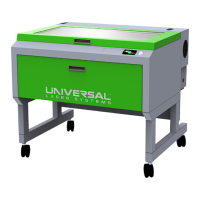
7. Locate and remove the 2 socket head screws securing the Z-Axis Stage Support and Table Support
Right.
7. Remove the 4 socket head screws, 4 lock washers, and 4 flat washers holding the Left Z-Axis Assembly
in place.
8. Remove the Left Z-Axis assembly from the system.
9. Installation is opposite of removal.
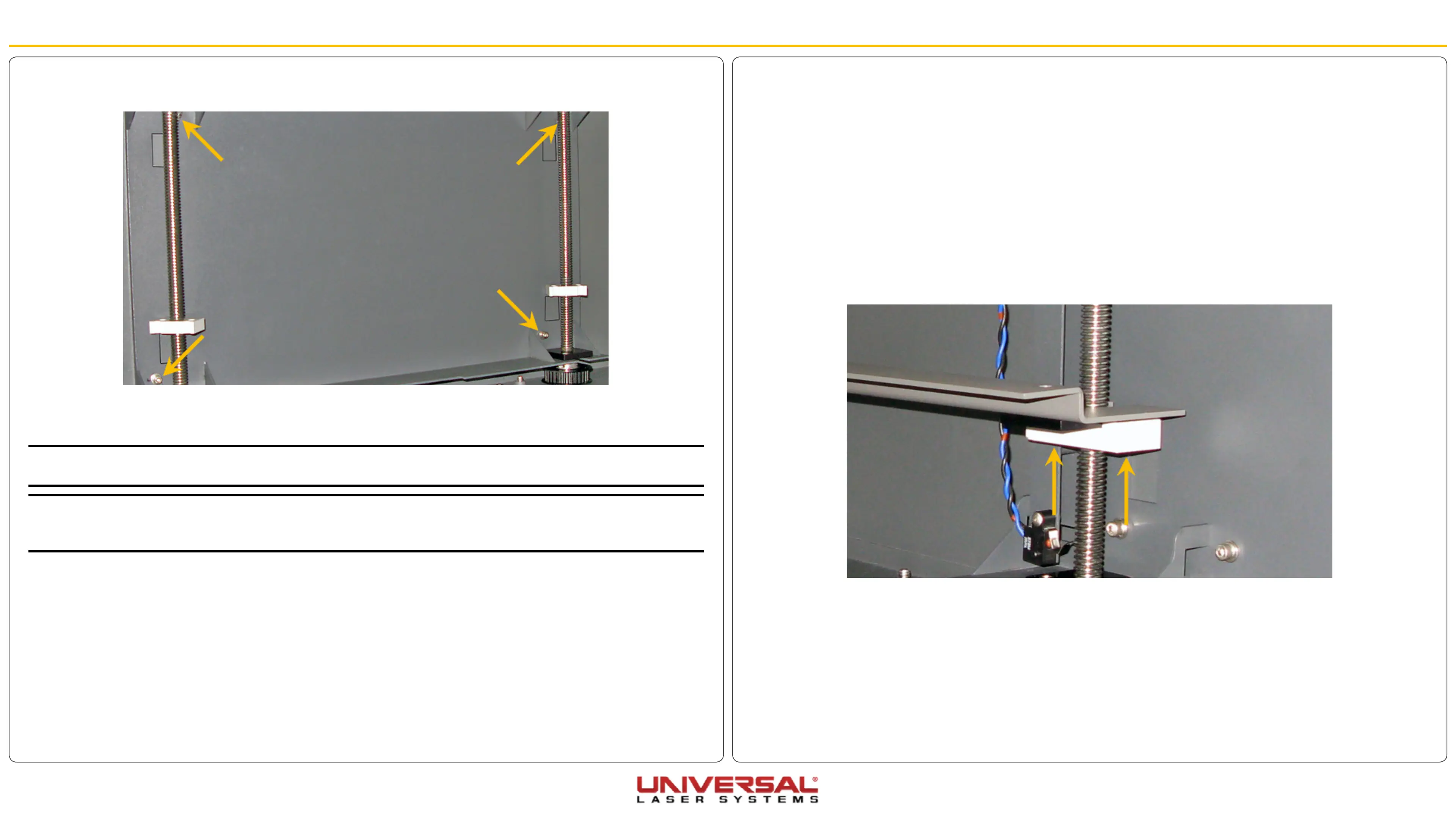
NOTE: When installing the Left Z-Axis assembly ensure that the lead screw nuts are roughly aligned with the
Right Z-Axis Assembly lead screw nut. Then follow the Z-Axis leveling procedure .
NOTE: If the stage appears to be binding and the Z-Axis leveling procedure has been completed, loosen the
screws holding the bearings blocks in position. Move the stage all the way to the top and all the way to the
bottom. Re-tighten the screws and test again.