VLS Service Manual - REV2015.04
Table of Contents
Electronics
Page | 70
Electronics
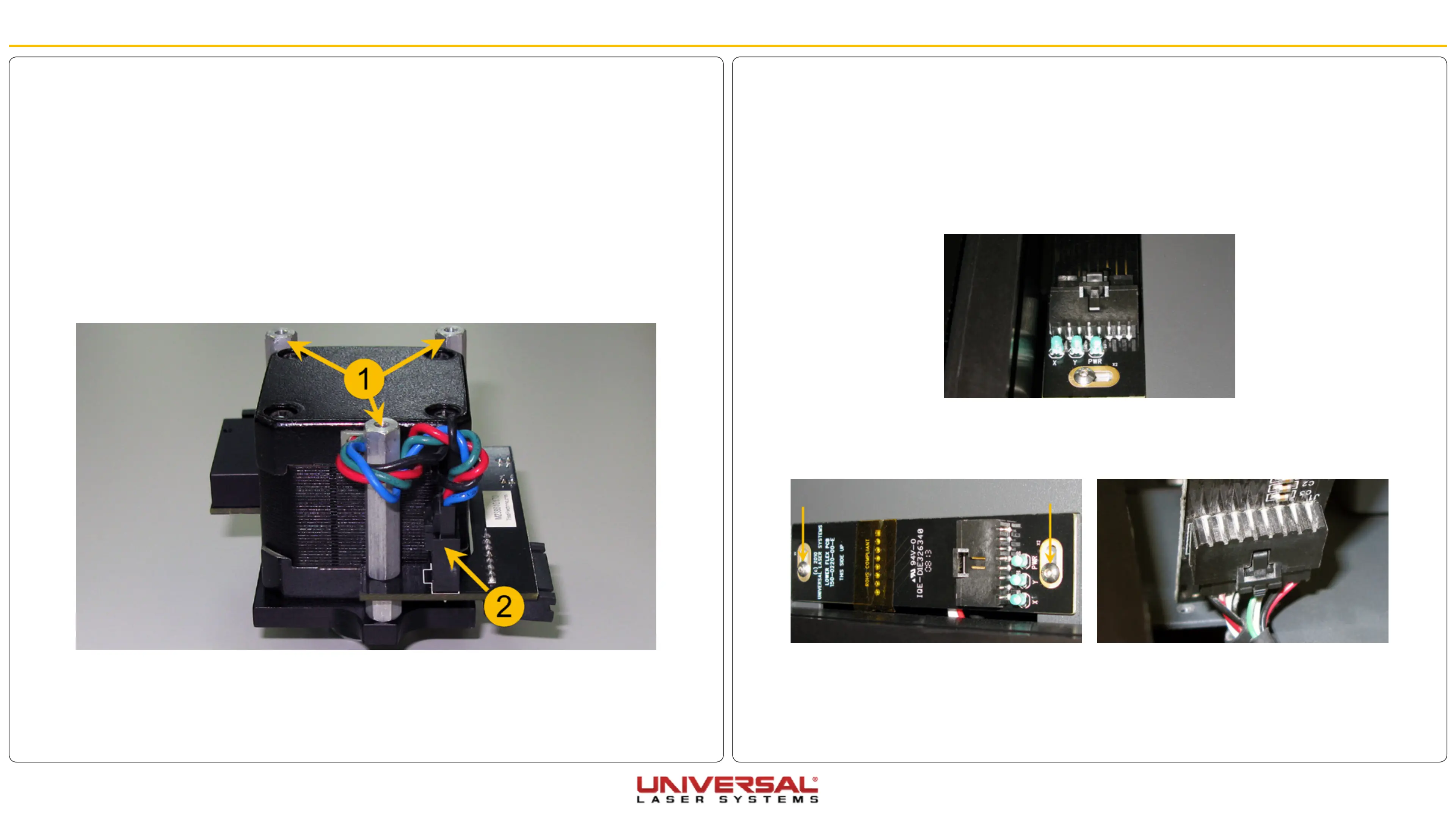
Lower Flex Board
1. Power OFF and unplug the VLS system.
2. Open the Top Door.
3. Move the X-axis arm toward the back of the system.
4. The Lower Flex Board is located on the right-hand side near the pressure cylinder. Unplug the Flex
Cable from the Lower Flex Board by pressing on the plastic tab and gently pulling the connector.
5. Unscrew the 2 screws that hold the board and set side in a safe place.
6. Grab hold of the Lower Flex Board and turn it around slowly. Unplug the cable attached on the back of
the board. DO NOT pull on the Lower Flex Board because it is still attached to the VLS.
7. Installation is opposite of removal.
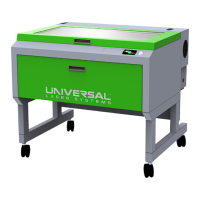
Upper Flex Board
1. Power OFF and unplug the VLS system.
2. Open the Top Door.
3. Move the X-axis arm toward the front of the system.
4. Locate and disconnect the Flex Cable from the Upper Flex Board by pressing the plastic tab on the
bottom side of the connector and gently pulling the plastic piece.
5. Remove the X-axis Motor Cover by removing the three Phillips head screws holding it. Set aside in a
safe place.
6. Remove the 3 standoffs (1) holding the Upper Flex Board in position.
7. Disconnect the X-axis Motor Cable (2) from the Upper Flex Board.
8. Installation is opposite of removal.