C
christophersimmonsSep 13, 2025
What does it mean if the 'Arm Down switch is ON, Arm is up' on Ultra Optics Rx?
- CChelsea HullSep 13, 2025
The Cylinder Down sensor is ON but the Cylinder Up solenoid and switch is ON.
What does it mean if the 'Arm Down switch is ON, Arm is up' on Ultra Optics Rx?
The Cylinder Down sensor is ON but the Cylinder Up solenoid and switch is ON.
Expresses gratitude for business and provides contact information for technical assistance.
Explains the meaning of various symbols and cautionary statements used throughout the manual.
Provides contact details for Ultra Optics technical service and support.
States that the product should not be modified and to refer to component manuals.
Information on how to obtain additional copies of the operation manual.
Details specific hazards like high voltage, UV light, hot surfaces, and chemicals.
Emphasizes the mandatory use of PPE, including gloves and safety glasses, when handling chemicals.
Specifies the need for accessible location and good ventilation for the machine.
Details required electrical power, compressed air, and deionized water for operation.
Describes the connection of power cord and foot switch to the machine.
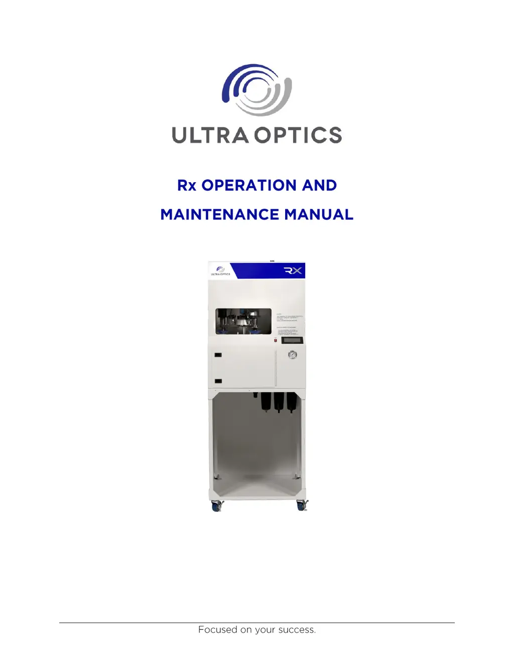
Provides a summary of the Rx's design and capabilities as a coating machine.
Step-by-step instructions for loading and unloading lenses into the machine.
Details the lens washing procedure using high-pressure deionized water.
Explains the lens drying method utilizing compressed air and filtration.
Describes the process of applying coating material to the lens surface.
Lists the sequence of steps to properly start the machine.
Describes the initial Human-Machine Interface screen for UV lamp warm-up.
Explains how to initiate a single lens processing cycle.
Explains how to initiate a two-lens processing cycle.
Describes accessing the machine setup configuration screen.
Describes accessing the detailed system information screen.
Describes accessing the diagnostic functions of the machine.
Step-by-step guide to perform a single lens processing cycle.
Important note regarding the use of the CYCLE STOP function for lens retrieval.
Step-by-step guide to perform a two-lens processing cycle.
Accessing the main menu and controlling core functions like coating and vacuum.
Detailed sequence to prime the wash pump for optimal operation.
Operating the UV lamp cycle and indexing the spindles.
Returns spindles to their home position.
Accesses the screen for UV lamp removal.
Setting and adjusting the time-out for the cover coating cycle.
Procedures for adjusting spindle speeds for coating and washing.
Buttons to position the UV lamp for removal or return to home.
Accessing vacuum tests, position checks, and alarm history.
Procedures to test vacuum on individual spindles.
Using INDEX and HOME INDEX for spindle positioning.
Visual screen to monitor machine positions and PLC inputs.
Screen displayed during lamp module cool down after power interruption.
Highlights the need for regular maintenance by trained technicians to ensure performance.
Provides a schedule for daily and weekly preventative maintenance tasks.
Lists quarterly maintenance tasks and their descriptions.
Detailed procedure for checking and adjusting spindle speeds.
Steps to set the wash speed for the spindle.
Procedure for adjusting the duration of the UV lamp cycle.
Steps for safely removing the UV curing lamp module.
Procedure to set the correct coating discharge height.
Steps to prime the wash pump for optimal operation.
Procedure to ensure the lens is completely dry before coating application.
Detailed instructions for replacing the coating filter, including priming.
Safe procedure for retrieving lenses from the UV light module.
Comprehensive steps for removing and reinstalling the UV light module.
Procedure for flushing the coating system, including cleaning and re-priming.
Instructions for replacing HEPA pre-filters, main HEPA filter, and air filter packs.
Procedure for replacing the UV light module.
Instructions for replacing suction cups on the spindles.
Steps for replacing proximity, lift cylinder, and vacuum sensors.
Detailed procedure for replacing the entire spindle motor assembly.
Steps to adjust the air regulator to the specified pressure.
Lists and describes the PLC output signals and their functions.
Lists and describes the PLC input signals and their functions.
Lists commonly replaced parts with part numbers.
Lists consumables like gloves, wipes, and cleaning agents.
Addresses the wagon wheel effect and suggests adjusting coating height.
Guides on resolving streaks from filter air and tiny pits from wash tips.
Explains causes for pits on lens edges and suggests adjustments for air jet and pump prime.
Discusses troubleshooting large pits and runs, often due to debris.
Addresses issues with glob of coating on the lens, checking spindle and bearings.
Lists critical alarms that stop the lens cycle and their causes.
Lists non-interrupting alarms displayed on the operator's screen.
Outlines the warranty period and conditions for new equipment.
Defines limitations on the corporation's liability for delays or unforeseen events.
| Brand | Ultra Optics |
|---|---|
| Model | Rx |
| Category | Industrial Equipment |
| Language | English |