-10-
3.4 Electric wiring
3.4.1
Single phase motor specification
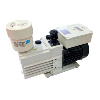
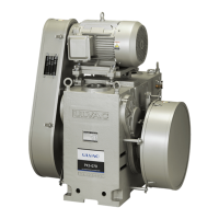
(1) This pump has performed beforehand electric wiring by the side of a pump.
(2) Please insert the plug of the power cord of a pump in the wall socket of single phase 100V.
(3) Fault load protection equipment (manual return type thermal protector) is built in this motor.
3.4.2
Three phase motor specification
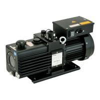
(1) This pump has performed beforehand electric wiring by the side of a pump.
(2) The rotation direction of this pump is seen from the pump front (level gauge side), and is a
clockwise rotation.
(3) If it wiring like fig.6, the rotation direction of a pump will be seen from the pump front
(level gauge side), and will be rotated clockwise. When you rotate in the opposite direction,
please shut off a power supply immediately, replace wiring connected to U and W, and
check rotating in the right direction anew.
(4) When you form fault load protection equipment in the exterior of a 3-
phase motor, please
refer to table 2.
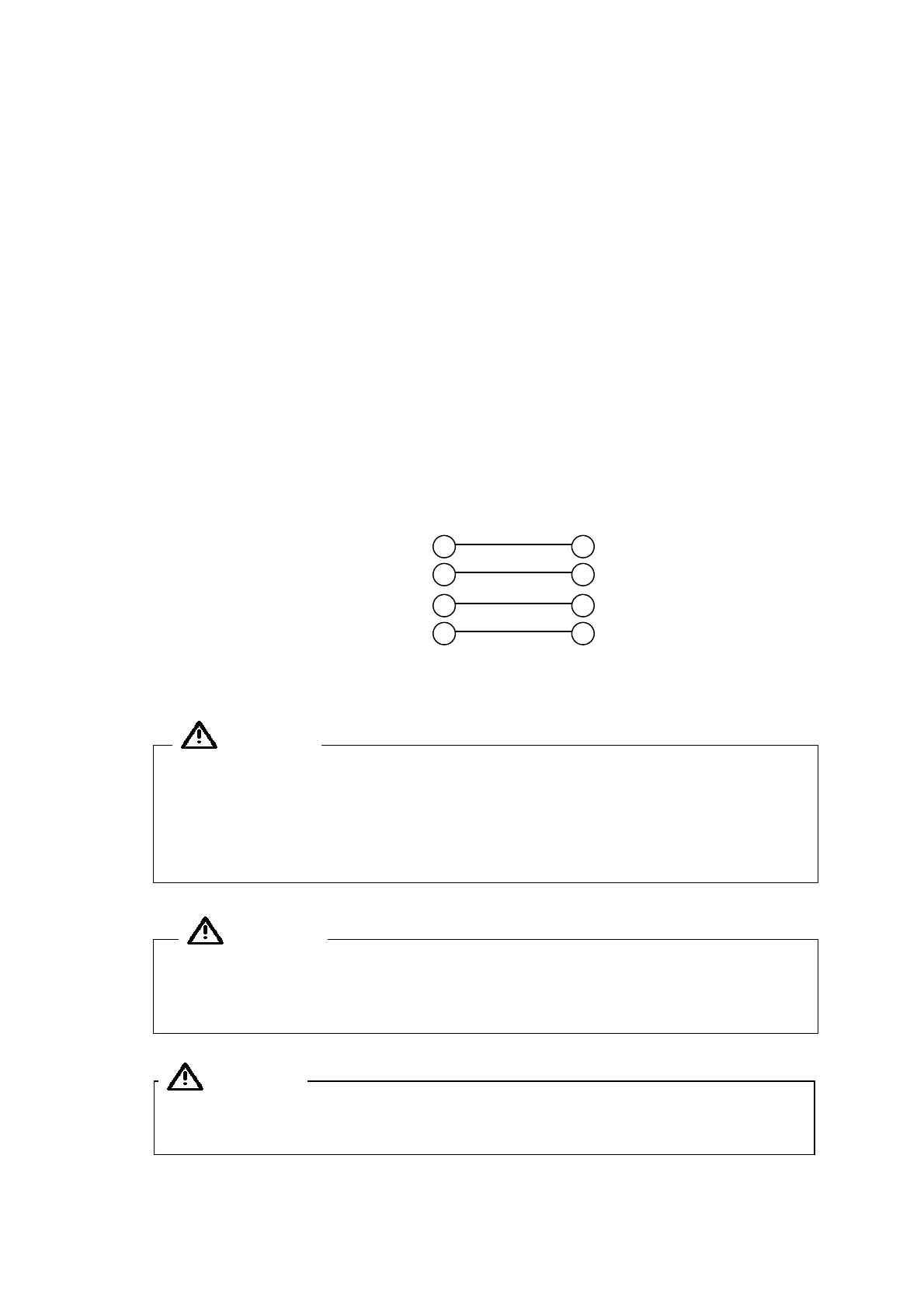
A motor side grounding terminal is the screw with a display of "E" of the main part rear of
a motor.
AC 200V 50Hz/60Hz Ground E
3-phase Power supply R U
AC 220V 60Hz S V Pump・Motor
3-phase Power supply T W
Fig. 6 Electric wiring diagram
Before connecting wires, turn off the power switch. Never perform wiring with
the power supplied as an electric shock will occur. Connect the earth wire
correctly. Failure to do so may result in electric shock if a failure or earth
leakage occurs. Installation of a dedicated earth leakage breaker is also
recommended.
Perform electric wiring correctly in accordance with the “Electric Equipment
Technical Standard” and “Internal Wiring Regulation.” Incorrect wiring
will result in fire.
If the pump is directly (and permanently) connected to the host equipment
then the end-user has to provide adequate disconnection device.
Warning
Warning
Caution