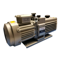
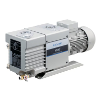
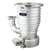
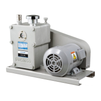
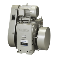
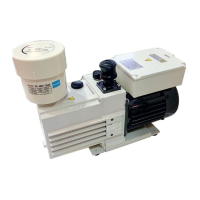
This document is an instruction manual for the ULVAC Oil Sealed Rotary Vacuum Pumps, models VD151 and VD201. It provides detailed information on the product's function, technical specifications, usage, and maintenance.
Function Description
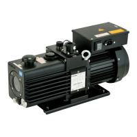
The ULVAC VD151 and VD201 are compact, low-noise, Gaede type two-stage vacuum pumps designed to permit high-speed rotation. They are constructed to be easily maintained and repaired. These pumps are equipped with a lubrication pump system, an hydraulic oil anti-sucking system, and a variable oil level system. The lubrication pump system ensures continuous pumping operation under near atmospheric pressure. The hydraulic oil anti-sucking system prevents oil from flowing back to the cylinder if the power fails or the pump stops for a long time without venting the intake side to atmospheric pressure, making restart difficult. The variable oil level system allows for easy control of the oil level, and the pump is operable if the oil level is within its oil level indicating range during operation. Additionally, these pumps are installed with a gas ballast function as standard, which effectively pumps condensable gas, such as water content and organic solvents.
Important Technical Specifications
The VD151 and VD201 models have distinct specifications:
VD151:
- Pump Weight: 29kg
- Motor: 3-phase, 0.55kW, Totally-Enclosed Fan-Cooled Flange Induction Motor
- Rated Current (200V-240V/50Hz): 2.90A (200V), 2.70A (220V), 2.60A (230V), 2.60A (240V)
- Rated Current (380V-460V/50Hz): 1.60A (380V), 1.60A (400V), 1.60A (415V), 1.70A (460V)
- Rated Current (200V-240V/60Hz): 3.10A (200V), 2.90A (220V), 2.80A (230V), 2.70A (240V)
- Rated Current (380V-460V/60Hz): 1.70A (380V), 1.60A (400V), 1.60A (415V), 1.50A (460V)
- Ultimate Pressure (GV Close): 0.67 Pa
- Ultimate Pressure (GV Open): 6.7 Pa
- Oil Requirement: MAX 0.7 L
- Recommended Oil: ULVOIL R-72 (Standard), ULVOIL R-42 (Cold area or winter time)
VD201:
- Pump Weight: 34.5kg
- Motor: 3-phase, 0.7kW, Totally-Enclosed Fan-Cooled Flange Induction Motor
- Rated Current (200V-240V/50Hz): 3.60A (200V), 3.30A (220V), 3.20A (230V), 3.10A (240V)
- Rated Current (380V-460V/50Hz): 1.90A (380V), 1.80A (400V), 1.80A (415V), 1.70A (460V)
- Rated Current (200V-240V/60Hz): 4.00A (200V), 3.70A (220V), 3.60A (230V), 3.50A (240V)
- Rated Current (380V-460V/60Hz): 2.10A (380V), 2.00A (400V), 2.00A (415V), 2.10A (460V)
- Ultimate Pressure (GV Close): 0.67 Pa
- Ultimate Pressure (GV Open): 6.7 Pa
- Oil Requirement: MAX 0.7 L
- Recommended Oil: ULVOIL R-72 (Standard), ULVOIL R-42 (Cold area or winter time)
Both models incorporate a temperature sensor (PTO) which opens at 150°C. The bimetallic strip, indirectly heated, with normally closed (N/C) contact, cuts off at 2.5A at 250V with cosφ0.4.
Usage Features
Installation and Storage:
- When taking the product from the box, use cargo-handling equipment such as a crane utilizing the eyebolt located at the upper part of the pump. Confirm no abnormality before using the eyebolts.
- Only technically entitled personnel should conduct unloading and operating the unloading machinery.
- Pump drop or lay down due to unreasonable operation or machinery setup is strictly restricted.
- Wear leather gloves and use appropriate tools to prevent injury during handling.
- The pump should be installed horizontally in a place with less dust and humidity, allowing for easy maintenance.
- The rubber leg is attached to the base, allowing horizontal installation without rattling.
Operation:
- Do not run the pump by blocking the exhaust outlet or putting any device that might hamper gas passage onto the outlet, as this can cause a pressure rise inside the vacuum pump, leading to oil leak or oil level gauge resulting in overload of the motor.
- The product is not made as a withstand pressure structure. The ensured pressure value of the pump is 0.03MPaG (0.3kg/cm²G) (Gauge pressure).
- Always ensure the valve is put to a pipe after the exhaust outlet, and check and ensure that it is open.
- Turn OFF the Power Supply to execute check and repair.
- Do not touch the motor, vacuum pump or piping during pump operation and just after stopping it while the pump unit keeps high temperature.
- If the pump is used to exhaust toxic gas, the pump oil will become toxic. Pay full attention.
- The vacuum pump gets high temperature during operation. VD151: temperature increase under non-load operation: 25°C, temperature increase under high-load operation: 45°C. VD201: temperature increase under non-load operation: 20°C, temperature increase under high-load operation: 78°C.
- Refrain from touching the motor and pump unit until the pump cools down after having stopped operation.
- Refrain from touching any part other than the valve when operating the gas ballast.
- Ensure to close the gas ballast to start the operation.
- The oil might jet out during operation around high pressure range.
- Oil mist would appear through the exhaust side if operated around high pressure range.
- The gas ballast valve should be kept closed when not exhausting the condensed gas to prevent oil splash, power loss or ultimate pressure rise.
- The guaranteed pressure resistance of this pump is 0.03 MPa (0.3 kg / cm2) (gauge pressure). Operate the supply pressure of the gas ballast gas to be introduced within the following range. Supply pressure: Atmospheric pressure to 0.03 MPa (0.3 kg / cm2 (gauge pressure)) or less.
- It is better to use the ULVOIL R-42 having less viscosity that enables you to start rotating the Pump around 4°C.
- You should, however, replace it with the ULVOIL R-72 if the temperature gets 10°C or more. Be cautious as using the ULVOIL R-42 in warm season would cause such troubles as sealing error, oil leak or more serious trouble, due to its lower viscosity.
- ULVOIL R-42 is unified for high load operation. When performing the high load operation, use ULVOIL R-72, and either warm the pump oil or perform the pump jog at several times, and the start up it.
Electrical Connection:
- Conduct the electrical connection referring to the provided figures.
- Use crimping terminals for the connection and tighten screws. Fix the connector tightly.
- Motor rotation direction is counterclockwise viewed from the motor side.
- Put a safety circuit such as an electromagnetic breaker for the electrical connection.
- Install and operate the product in compliance with laws and regulations relating to safety (e.g., Fire Defense Law, Electric wiring regulation).
- Install an overload protector suitable for the capacity of the motor. If an overload protector is not installed, or if an overload protector that is unsuitable for the motor capacity is installed, the motor will be damaged leading to fire.
- Turn OFF the Power Supply to do the electrical connection. Never try to work on it on keeping the electricity turned ON.
- Make sure to have steady grounding to prevent electrical shock.
- The screw of the earth terminal at the motor side is provided with an "earth mark" in the terminal box.
- Use power cords of the same diameter for the motor and earth.
- Use the pump only at the rated voltage. Use at other than the rated voltage will interfere with correct operation of the overload protector, and result in the motor burning out, or fire.
- The connector in the terminal box, with 380V-460V and 200V-240V power supply voltage, please change the wiring.
- Be sure to put an overload protective device conforming to the motor capacity.
- You have a risk that the Motor burns out or causes a fire if you have not put such an overload protective device or put a device not conforming to the motor capacity.
- You are also recommended to put a dedicated ground-fault interrupter.
- Do the correct wiring work conforming to the Electrical Installation Technical Standard and Internal line cord. Wrong wiring work might cause a fire.
- The larger cable gland is for wires having a diameter of φ8 to φ13, and the smaller one is for wires having a diameter of φ5 to φ8. Use a cable gland that is suitable for the size of the power cord to be used.
- Never fail to close the Terminal box cover to operate the Pump.
- Be sure to use different power cords for the motor and for taking out a temperature sensor signal.
- Apply a voltage of 250 V or less to the wire for taking out the temperature sensor signal. Connect a fast-acting an fuse having a capacity of 250 V, 2.5 V between the relay circuit and temperature sensor.
Maintenance Features
Oil Management:
- The pump oil might deteriorate in a shorter time depending on the use. It is recommended to replace the first pump oil within ten days after operation start and see how it got dirty to determine the oil replacement cycle.
- If the pump breathes in a lot of water or the like, you should replace the oil more frequently. It would deteriorate lubrication of the oil and further help corrosion of the pump inside and result in causing a failure. Do not store the product keeping sucked the water.
- If the pump breathed in chemical material such as acid, immediately replace the oil as it would cause the rust during the stop in one night to make the system not applicable to operate.
- You should also replace the oil if breathed in the solution to deteriorate lubrication of the oil as it would also cause biting inside. You shall have a risk if breathed in the solution in operation even you replaced the oil.
- Continuous operation one hour or more under high pressure 1000Pa or more would increase the oil volume that are discharged as the oil mist and cause rapid parts wear or cause a trouble such as burning.
- You are recommended to control the oil level on regularly supplying the pump oil. The maintenance cycle might become shorter.
- Upon continuously operating with high inlet pressure, the oil temperature becomes very high temperature. As a result, the oil sharply deteriorates, and the attained pressure and the exhaust speed go bad, and it causes the failure such as high speed abrasion of the parts and burn-in. Frequently perform replacement of the pump oil.
- The oil level should be between the two level lines (MAX and MIN) on the oil level gauge.
- The oil level gauge is for checking the pump oil level. Since the oil is not circulating between the pump case and the oil level gauge, contamination or discoloring of the oil may not be observed on the oil level gauge. Periodically drain approx. 50 ml of oil through the drain valve and check the oil for contamination and discoloring.
- Recommended replacement cycle of the vacuum pump oil:
- Vacuum system for study / laboratory, small vacuum system: Within 6 month ~ 1 year
- Vacuum system for production, vacuum evaporation: Within 3 ~ 6 month
- Vacuum valve exhaust system, large vacuum evaporation system: Within 3 month
- Metallurgy vacuum system such as thermal treatment, melting and the like: Within 1 month
- High vacuum dry, vacuum impregnation, vacuum formation and vacuum packing system: Within 1 month
- Low vacuum dry, pug mill and food packing system: Within 1 week
- When temperature is low, and a pump does not run, warm up the pump oil or turn the pump on and off several times in short intervals.
- When the pump stops after run for several seconds, you try to move it while putting slow leak in it, there is the thing that the pump can run consecutively (refer to fig.5).
- As the pump warmed, you close the slow leak valve, and please return it to regular running.
Oil Mist Trap:
- The oil mist trap can be mounted to trap the oil mist discharged from the pump.
- The TMX-1 model is for the VD151/VD201. The trap with adapter can be set on the pump instead of the original exhaust pipe at the outlet.
- At the outlet of the pump, remove the original exhaust pipe.
- Assemble the adapter and TMX-1 to establish the pump.
- Between the adapter and TMX-1, put the O-ring(G85).
- Four small screws and washers fix adapter and TMX-1.
- When the adapter is attached to the TMX-1, please remove the baffle inside the trap.
- Between the pump and adapter, put the O-ring(G30). Please set up the exhaust vent.
- Provide the time to return oil from TMX-1. When using VD151/VD201 at 10,000Pa or more, arrange so that the oil returns from TMX-1 to the pump making the not exhausted time (5 minutes) once every 30 minutes.
- Upon continuing the continuous exhaust at high pressure, the oil blocks the filter, and the pressure on the exhaust side becomes high, and the oil blows out from the exhaust port, and also the pressure may go bad due to the oil shortage in the pump.
- To use the Oil mist trap, be cautious not to have clog of the filter in the trap. Too much clog would prevent the exhaust gas from passing through the filter, raise the pressure inside the Pump unit (include the oil mist trap) and might result in breaking it.
General Maintenance:
- You should check following points at least once per three days while you continue operation.
- Check the machine more frequently during high overload operation (continuous operation 1kPa or more, repeated exhaust atmospheric pressure – vacuum).
- Whether the Vacuum oil pump oil volume is between two level lines or not.
- Whether the Vacuum pump oil is discolored or not.
- Whether there is no foreign noise.
- Whether there is anything strange in the Motor current value.
- Whether there is no oil leak from the pump.
- Be sure to turn OFF the Power Supply to execute check and repair.
- Person other than Repair technician should not be in charge of dismantling, repairing or remodeling the product.
- You have a risk of getting injured or electrical shock by a fire or erroneous move.
- Should you found any malfunction or error, just turn OFF the Power Supply to prevent accident and ask the agency or closest Service Center for check and repair.
- The pump system needs repair if occurred any oil leak from the Shaft sealing or Pump unit. Type of the seals and O-rings are listed at the end of this document. Please contact the Service Center close to you for purchase and repair.
- When used the Gas ballast function, the valve or in the introduction passage inside the Pump may be stuck in the dust. Replacement parts and repair support at the local service center.
- The Suction inlet might be clogged by the dust contained in the gas breathed in from the Vacuum chamber and thus the Pump performance might be impaired. If there is the metal mesh is dirty, please wash that.
- Further it is anticipated that any welding scale drops off in the pipe particularly at the beginning of the system start. Be fully cautious.
- Checking around the pump:
- Check whether bolts and nuts and the like fixing the pump are loose or not.
- Check whether pipes connected to the inlet/outlet are loose or not.
- Check and ensure that there is no leakage from the piping and valves.
- Checking the pump: Please refer to the "6.5 Trouble check list." Should the condition was not recovered after having checked points indicated there, please contact the closest Service center.
- The spider of the coupling that connects the pump body and the motor is made of rubber. Replace it if the spider is damaged. Please contact the closest Service center.
- Replace it once a year by rule of thumb. If the pump is started and stopped several hundreds of times a day, however, shorten the replacement frequency.
- Stop the pump and turn OFF the Power Supply. Disconnect the power cable of the motor.
- To take out the spider, remove which fix the motor to the pump main unit, and remove the motor. Then the coupling can be removed and the spider taken out.
- After inspecting the spider, mount the spider to either of the two coupling, and adjust the position so that both claws of the couplings are engaged with each other as shown in Fig. 11.
- Put the four bolts (M6x20) removed in the item (3) above. (Recommended tightening torque: 10 N·m)
- Execute the wiring.
- Connect the concave section (female) of the pump unit with the convex section (male) of the motor, push the motor into the pump so that both connecting surfaces come completely into contact with each other, and fix the motor with bolts.
- If you leave the drain valve semi-open for several months, it might get reshaped that you might not be able to shut the pump all the way. When storing the pump, please make sure the valve is completely shut. If you are using the plug instead of valve, the same situation will be applied.
- Long term storage of the Vacuum pump without operation might possibly cause trouble in operation caused by rust. If you kept the Pump long time without operating it, ask a closest Service Center for the check.
- If there found remarkable Pump contamination or performance deterioration due to the operation condition, you are recommended to conduct regular overhaul regardless of the check items described above.
- Overhaul shall be required to keep the performance as well as the safety and further to continue the production on forecast.
- Please contact the Service Center close to you listed at the end of the document as for the overhaul.
- Do not remember to fill and submit the Contamination certificate enclosed in the end of the document.
- We would be obliged to refrain from handling and/or executing maintenance of the product if the detail of used hazardous substance was not disclosed or the product has exhausted such substance that the detoxification process is hardly conducted.
- You are requested to conduct the overhaul once a year.
- If there found remarkable Pump contamination or performance deterioration due to the operation condition, you are recommended to conduct the overhaul earlier than one year period.
- You shall be in need of replacing such parts as listed on the "9. Main spare parts" at minimum.
Disposal:
- Make sure to keep in compliance with the laws and regulations established by the local governments to dispose the Vacuum pump. You should ask the dedicated disposal agency for the disposal particularly if the Pump has exhausted any toxic gas.
- You should ask a special disposal agency for the disposal particularly if the Pump has exhausted any toxic gas hazardous to the human body. The Pump oil as well as the Pump unit gets hazardous.
- Even if you do not have harmful gas emissions, is at the disposal of oil, Material Safety Data Sheet is provided, “DISPOSAL CONSIDERATIONS” read, please discard the oil.