6
2.Observe the waveform displayed.
Excessive compensation Correct compensation Insufficient compensation
Picture 1-2 Probe compensation calibration
3.If the displayed waveform does not look like the above “correct compensation”
waveform, use a non-metallic screwdriver to adjust the probe’ s variable
capacitance until the display matches the "correct compensation" waveform.
Warning: To avoid electric shock when measuring high voltage using
the probe, please ensure that the probe insulation is in good condition
and avoid physical contact with any metallic part of the probe.
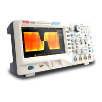
1.3 Front Panel
1 2 3
4
5
6
7
8
9
10
1112 13141516171819
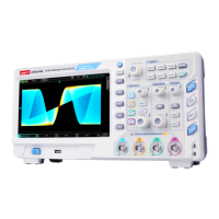
Picture 1-3Oscilloscope Front Panel
Screen display area
Multipurpose knob
Waveform recording setting
Shuttle knob
Function menu
Numeric keypad
Automatic setting
Run/stop
Single trigger
Clear all
Probe compensation signal connector and ground terminal
Factory setting, AWG (arbitrary waveform generator),
protocol decoding, print screen
Trigger control area
Horizontal control area
Analog channel input
Vertical control area
Menu control
USB HOST interface
Power on/off
1
2
3
4
5
6
7
8
9
10
11
12
13
14
15
16
17
18
19
 Loading...