10
1.6 User Interface
1 2 3
4
5
6
7
8
9
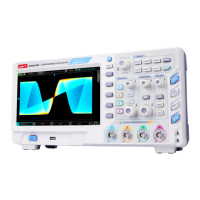
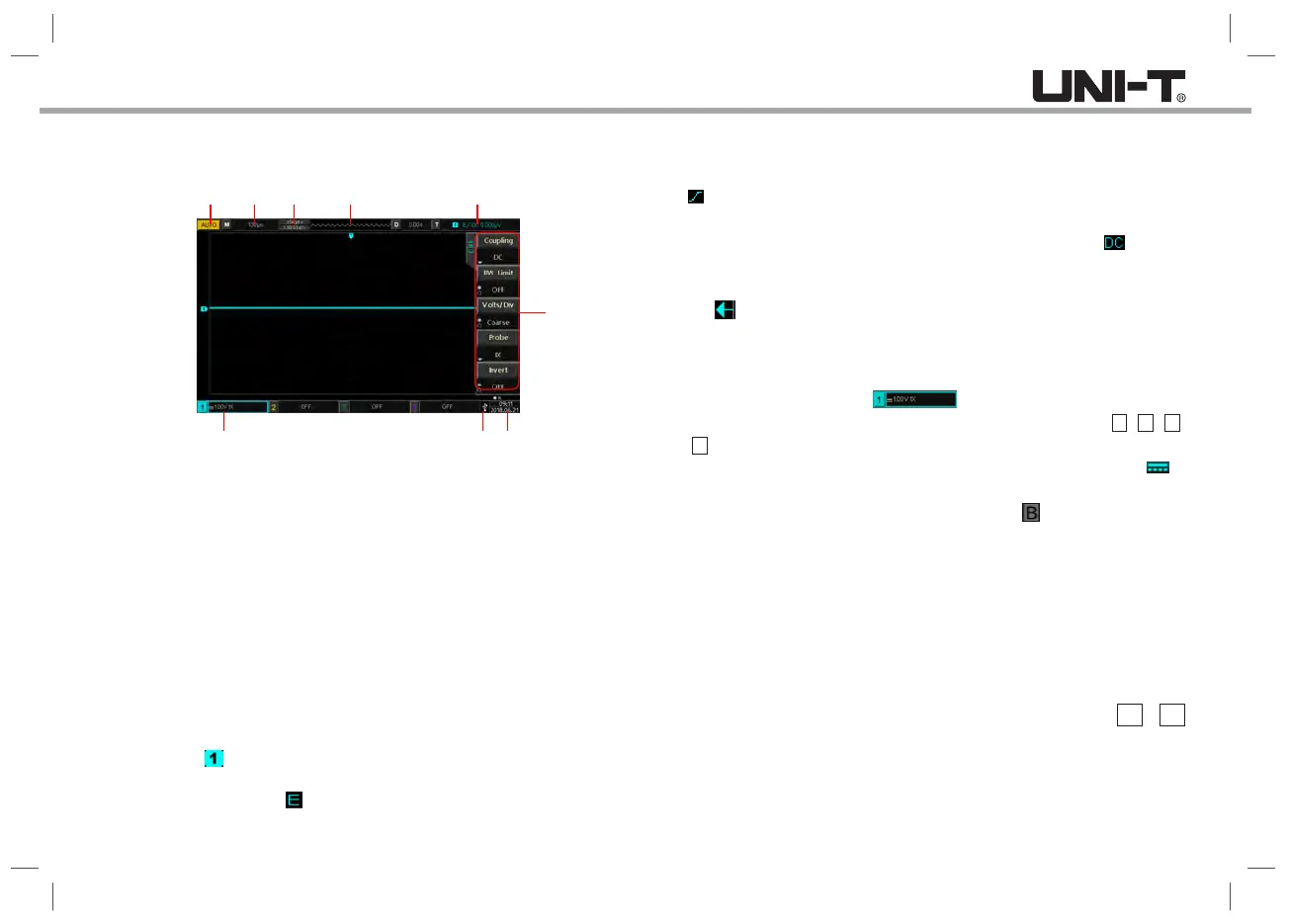
Picture 1-5Oscilloscope display interface
①.Trigger Status Identification: Includes TRIGED (has been triggered),
AUTO, READY, STOP, and ROLL (rolling).
②.Time Base Scale: Indicates the amount of time represented by one grid
on the horizontal axis, which can be adjusted by the horizontal SCALE
knob.
③.Sampling Rate/ Memory Depth: Indicates the current sampling rate and
storage depth.
④.Horizontal Displacement: Shows the horizontal displacement value of the
waveform, which can be adjusted by turning the horizontal POSITION knob.
Press the knob to return the displacement value back to 0.
⑤.Trigger Status: Displays trigger source, type, slope, coupling, level, etc.
a. Trigger source: There are seven states: CH1~CH4, AC Line, EXT,
and EXT/5. CH1~CH4 will each be of a different trigger color, for
example, is CH1.
b. Trigger type: The types are edge, pulse width, video, slope, and advanced
trigger. For example, is an edge trigger.
c. Trigger edge: The types are rising, falling, and any kinds. For example,
Indicates trigger at the rising edge.
d. Trigger coupling: The types are DC, AC, high frequency suppression, low
frequency suppression, and noise suppression. For example, indicates
DC coupling.
e. Trigger level: Indicates the current trigger level value, corresponding to
the on the right side of the screen. Adjust the LEVEL knob in the
trigger control area to change this parameter.
⑥.CH1 Vertical Status: Displays CH1 activation state, channel coupling,
bandwidth limitation, vertical scale, and probe attenuation coefficient.
Channel activation state: When the background includes
the channel color, the channel is activated. Press the button 1 , 2 , 3 ,
4 to activate or open/close the corresponding channel.
Channel coupling: Includes DC, AC, and grounding. For example, is
DC coupling in CH1.
Bandwidth limitation: Enable and there will be a icon shown on CH1
vertical status bar.
Vertical scale: When CH1 is activated, the vertical scale parameter can be
adjusted by the SCALE knob in the vertical control area.
Probe attenuation coefficient: Displays CH1 probe attenuation coefficient:
0.001X, 0.01X, 0.1X, 1X, 10X, 100X, 1000X.
⑦.USB Device Indicator: Displays the indicator when the USB device interface
is connected to a USB storage device such as a USB flash disk.
⑧.Current date and time.
⑨.Operation Menu: Displays the current operation menu. Press F1 ~ F5
can change the corresponding submenu content.
⑩.Analog Channels and Waveforms: Displays CH1 ~ CH4 channels and
waveforms, the color of the channel indicator is consistent with the
waveform.
 Loading...