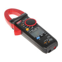
UT200A+/UT200B+ User Manual UT200A+/UT200B+ User Manual
Range AccuracyResolution
0.1Ω/0.001V
This is the 2-in-1 range
(continuity and diode)
used for automatic
measurement, the product
can identify automatically
as per the measured signal.
Automatic
identification
0.1Ω
Under open circuit, the
resistance is set as ≥50 Ω,
the buzzer keeps silent.
Under well-connected circuit,
the resistance is set as
≤30 Ω, the buzzer makes
sound continuously.
0.001V
Open-circuit voltage: About
2.2VTesting current: About
1.0mANormal voltage of
silicone PN junction:
About 0.5~0.8V
Overload protection: 600Vrms (DC/AC)
6. Capacitance Measurement (UT200B+)
Range Accuracy
30.00nF
300.0nF
± (4.0%+10)
3.000μF
30.00μF
Resolution
0.01nF
0.1nF
0.001μF
0.01μF
± (4.0%+5)
300.0μF
0.1μF
± (5.0%+10)
1.000mF
0.001mF
Overload protection: 600Vrms (DC/AC)
Range to ensure accuracy: 5~100% of range
XI. Maintenance
Warning: Before opening the rear cover, please the power is
the test leads are removed from input terminals and disconnected
circuit). with measured
1.General Maintenance
Clean the casing with wet cloth and mild detergent, do not
use abrasives or solvents.
In case of any abnormal situation, please stop use immediately
and perform maintenance.
Calibration or maintenance must be performed by qualified
designated technical department. professionals or
2. Battery Replacement
If low battery symbol “ ”appears on the LCD, please replace
the battery immediately, otherwise it can affect the measurement
accuracy.
Battery specification: AAA 1.5V×2
Set the power switch at “OFF”, remove the test leads from
input terminals.
Loosen the screw (pictured), remove the battery cover, and
replace the battery. Note the polarity when installing new
batteries.
Figure 4
15
16
5.Continuity and Diode Measurement
Screw
Battery cover
Battery