UT200A+/UT200B+ User Manual UT200A+/UT200B+ User Manual
≥2 seconds to turn on/off the backlight.mode; long press for
LIVE button: Short press this button at voltage mode to enter
measurement. /exit neutral and live
“ ”button (UT200B+): Under voltage, resistance and
capacitance modes, when this button is short pressed, the
product enters relative measurement mode and the symbol
“ ”is displayed. Long press this button to turn on/off the
flashlight turns off automatically after it is lit up flashlight, the
for 5 minutes.
“ ”button (UT200A+): Short press this button to turn on/off
the flashlight, the flashlight turns off automatically after it is lit
up for 5 minutes.
IX. Operating Instructions
Please check the battery before measurement, if the low battery
symbol “ ”appears on the LCD when powering on the product,
please replace the battery immediately. The symbol “ ”near
input terminals warns that the measured voltage or current cannot
exceed the specified value in order to ensure safety!
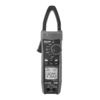
1. AC Current Measurement (Figure 2)
1) Select AC currents: 3A~, 30A~(UT200A+), 400A~(UT200A+),
30/600A(UT200B+).
2) Open the jaws to clamp one cable, make sure the clamp
3) The clamp meter can measure only one current conductor
at a time, if two or more conductors are measured at the same
time, the measurement result can be incorrect.
jaws are closed in place.
Figure 2
Note:
.The current measurement must be performed in 0°C~40°C
Do not release the trigger abruptly, the clamp meter is sensitive
cause reading to mechanical stress to some extent, impact can
variation in a short time.
Please place the measured conductor at the center of the
cause an error of ±1.5% of the clamp jaws, otherwise it can
reading.
If the measured current is ≥AC 400A (UT200A+) or AC 600A
(UT200B+), the product will sound an alarm and the high-
is displayed.voltage alarm symbol “ ”
Do not continue testing if “OL” is displayed (when the measured
410A for UT200A+ or AC 610A for UT200B+), current is over AC
otherwise it may cause product damage.
2. AC/DC Voltage and Frequency Measurement
1) Set the rotary switch to AC/DC voltage position
2) Connect red test lead with V terminal, and black with COM,
then the tips of both test probes respectively make contact
with both ends of the measured voltage (connect with the
load in parallel).
3) At AC voltage position, short press “SELECT” to enter voltage
frequency (10 Hz~10 kHz) measurement.
Note:
Do not measure voltage over 600Vrms for ACV/DCV
measurement. It is possible to measure higher voltage, but it
may cause product damage and personal injury! The input
7
8
Current measurement