Model UT58D: OPERATING MANUAL
19
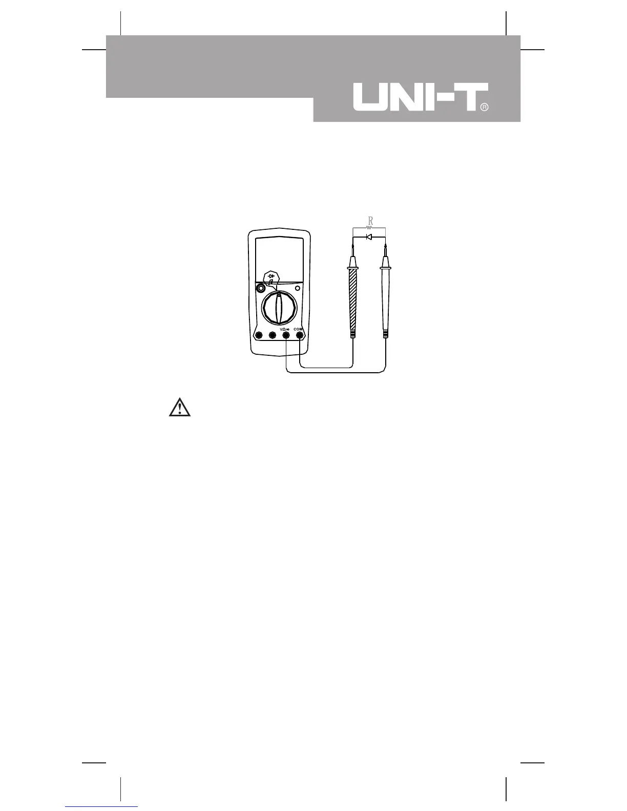
D. Measuring Diodes and Continuity (see figure 6)
Warning
To avoid damage to the Meter or to the equipment
under test, disconnect circuit power and discharge
all high-voltage capacitors before measuring diodes.
To avoid harms to you, never attempt to input voltages
higher than 60V DC or 30V rms in AC.
Measurement Operation(6)
( figure 6)
Black Red
1. Insert the red test lead into the V input terminal and
the black test lead into the COM terminal.
2. Set the rotary switch to an appropriate measurement
position in range.
3. Connect the test leads parallel across with the object
being measured.
The measured value shows on the display.
Measuring Diodes
Use the diode test to check diodes, transistors, and other
semiconductor devices. The diode test sends a current
through the semiconductor junction, and then measures
the voltage drop across the junction. A good silicon junction
drops between 0.5V and 0.8V.
To test out a diode out of a circuit, connect the Meter as
follows: