28
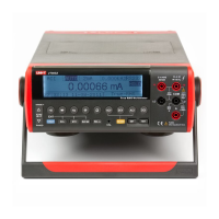
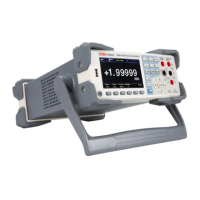
Model UT81B: OPERATING MANUAL
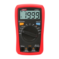
Ω
Note1. Insert the red test lead into the Ω terminal and the
black test lead into the COM terminal.
2. Set the rotary switch to
3. Connect the test leads across with the object being
measured.
4. The measured value shows on the display.
When measuring resistance, the corresponding
functional buttons:
RES REL Rang Rang
F1 F2 F3 F4
F1: toggle to diode mode
F2: relative mode
F3: select to a range up
F4: select to a range down
When measuring low resistance, the test leads can
add 0.1Ω to 0.2Ω of error to resistance measurement.
To test the leads, touch the probe tips together and
read the resistance of the leads. Take the reading
obtained to subtract the resistance of the leads to
get the final reading.
For high-resistance measurement (>1MΩ) or low
resistance measurement (<40Ω), it is normal taking
several seconds to obtain a stable reading.
The LCD displays “OL” indicating open-circuit without
input.
When resistance measurement has been completed,
disconnect the connection between the testing leads
and the circuit under test and remove testing leads
away from the input terminals.
l
l
l
l
 Loading...