20
Measurement Operation(7)
red black
( figure 7)
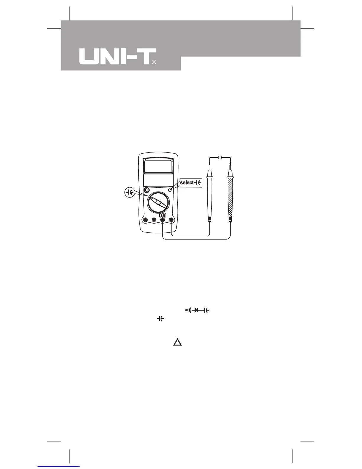
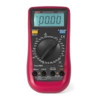
Model UT90C: OPERATING MANUAL
l When continuity testing has been completed,
disconnect the connection between the testing leads
and the circuit under test.
Capacitance Measurement (see figure 7)
The Meter’s capacitance ranges are: 40.00nF, 400.0nF,
4.000µF, 40.00µF, and 100.0µF. To measure capacitance,
connect the Meter as follows:
1. Insert the red test lead into the HzVΩ terminal and
the black test lead into the COM terminal.
2. Set the rotary switch toΩ and press SELECT
button to select measurement mode. The existing
of the Meter built-in equalized capacitance will affect
the accuracy. To increase the accuracy of capacitance
measurement, press button before measuring to
make the LCD display 0.
3. Connect the test leads across with the object being
measured.
The measured value shows on the display.
Note
l The LCD displays OL indicating the capacitor is short
-circuited or the capacitor value being tested is overload.