UTD2000 Series User Manual
50
example, if the pulse is a logical signal of TTL level, the trigger level should be set at about
2V and the trigger edge should be set to rising edge trigger. If you
are not certain about
the signal, you can observe it by automatic or
normal trigger to determine the trigger level
and trigger edge.
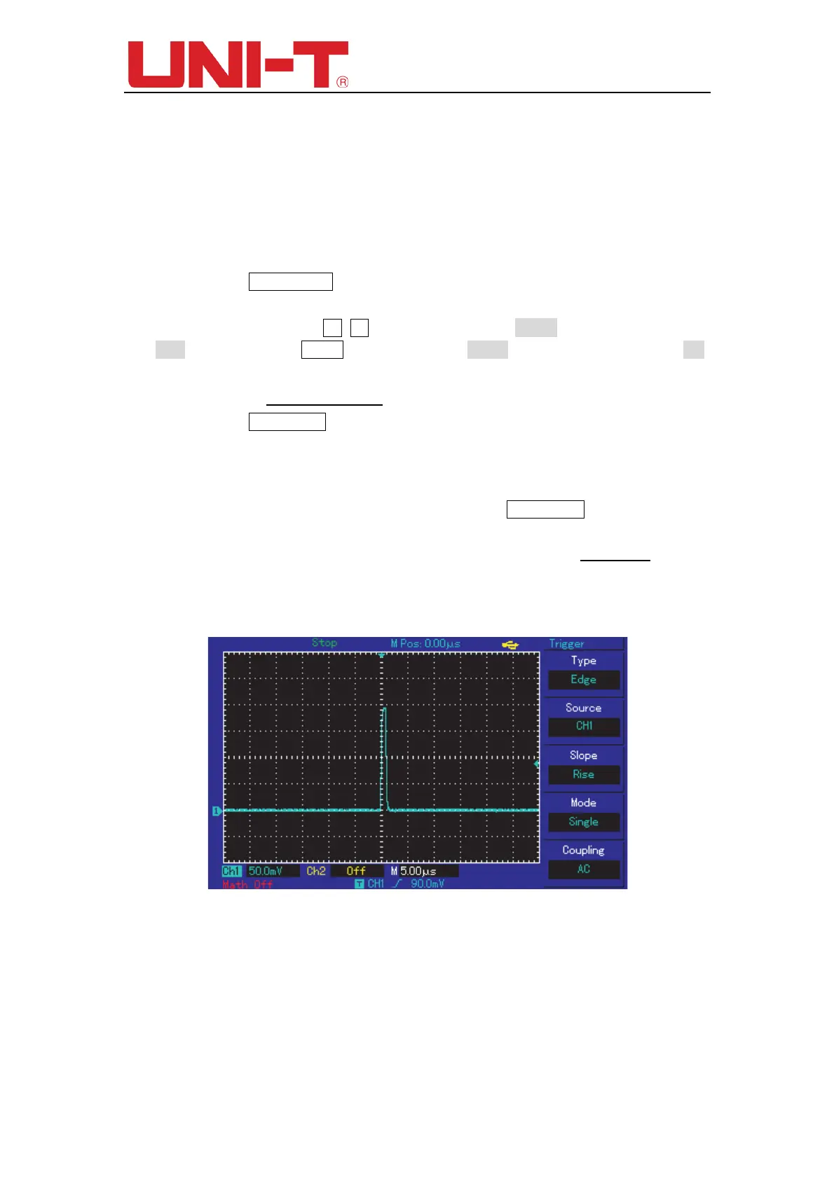
Steps :
(1) As in the previous illustration, set the attenuation factor of the
probe and CH1.
(2) Carry out trigger setup
① Press TRIG MENU in the trigger control zone to display the trigger setup
menu.
② In this menu, use F1~F5 set the trigger type to EDGE, set trigger source to
CH1, set inclination to Rising, set trigger type to Single and set trigger coupling to AC.
③ Adjust horizontal time base and vertical range to an appropriate range.
④ Turn the TRIGGER LEVEL
control knob to get the desired
⑤ Press RUN/STOP and wait for a signal that meets the trigger
condition. If any
signal reaches the set trigger level, the system will sample once and display it on the
screen. By
using this function you can easily acquire any occasional event. For
example, when a sudden glitch of relatively big
amplitude is acquired : set the trigger
level to just higher than
the normal signal level. Press RUN/STOP and begin waiting.
When a glitch occurs, the machine will automatically trigger and record the waveform
immediately before and
after triggering. By turning the horizontal POSITION knob in
the horizontal control zone on the front panel, you can change the trigger position
horizontally to achieve negative delay
trigger of various lengths for easy observation
of waveform
occurring before the glitch
Figure 12-3 Single signal
Example 4: Reducing random noise of signals
If the signal being measured is stacked with random noise, you can adjust the setups
of your oscilloscope to filter or reduce the noise, so it will not cause interference to the
signal during measurement. (Waveform is shown below)
 Loading...