Bulletin 30-020.007
Copyright © 2019 Unico Inc. Page 12
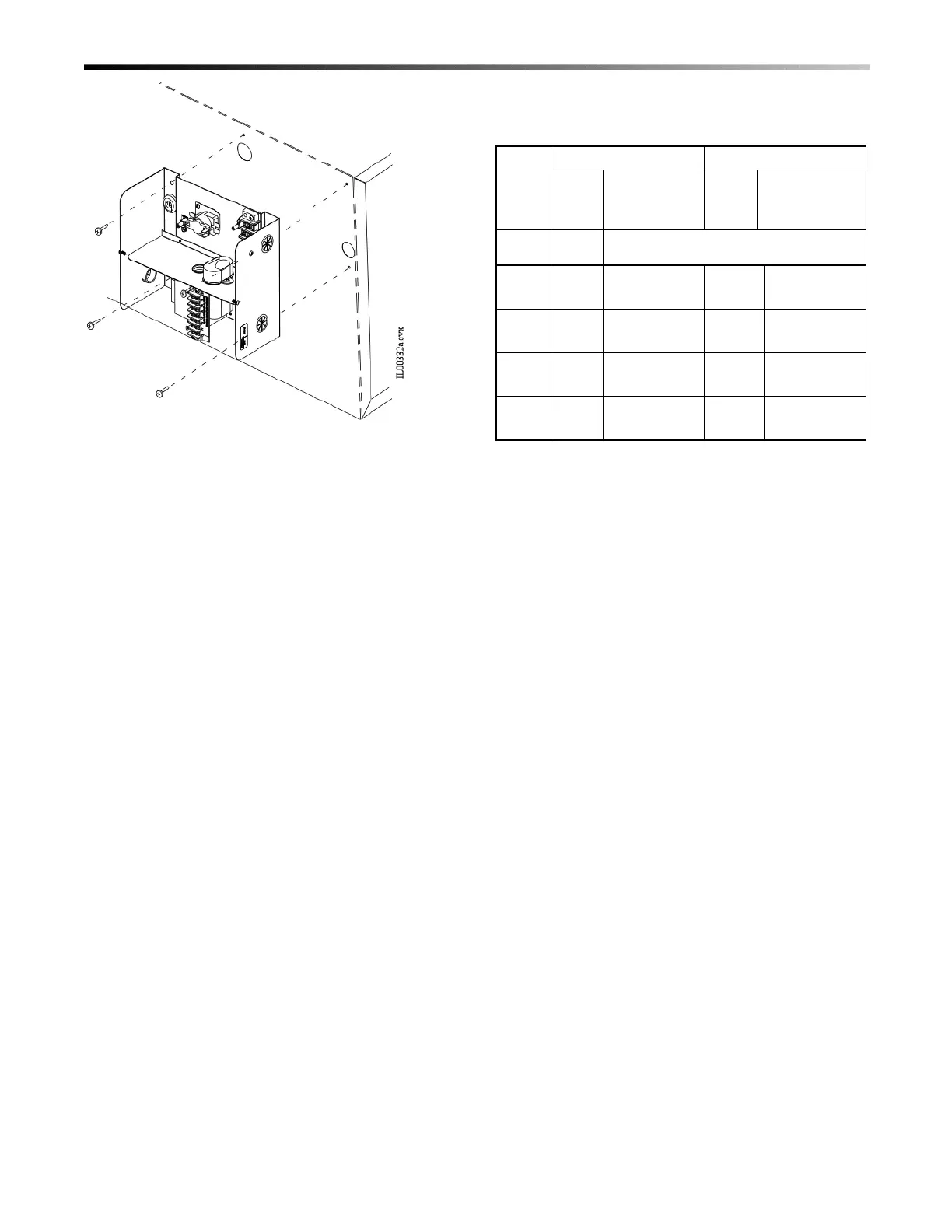
Figure 12. Control Box Mounting
Secondary Drain Pan Installation. Where an
overflow of condensate could cause water damage, a
secondary drain pan MUST BE INSTALLED. Place
the drain pan on the mounting base, platform or angle
iron support frame. Be sure to allow enough room for
the drain line and connection (refer to Table 3). The
assembled unit should be placed over the secondary
drain pan supported by rails with rubber pads for
isolation to raise the unit above the 1.5-inch (38mm)
sides of the secondary drain pan.
Table 2 shows the secondary drain pans to be used for
horizontally mounted modules. For vertical up-flow
arrangements that use the cooling module, the 2module
drain pans can be used where space permits and the
return air is entering from the side. These pans would
be over-sized compared to the footprint of the cooling
module. If a smaller drain pan is necessary, it should
be fabricated to be at least 1-½-inch (12.7 mm) larger
on each side of the bottom module.
For vertical down flow (counter flow) arrangements it
is difficult to provide a secondary drain pan because of
the blower discharge at the bottom. The secondary
drain pan must be fabricated with an opening for the
blower discharge and plenum adapter and still provide
a sealed drain pan.
Table 3. Secondary Drain Pan Dimensions, in
(mm)
† NOTE – The drain fitting extends 7/8 inch (22 mm) beyond this
dimension.
Like the modules, all the secondary drain pans except
UPC-24D will fit through the return air opening. For
these drain pans it will be necessary to fold the pans in
order to pass through the return opening. If you are
unable to use the UPC-24D because of space
limitations, use the UPC-24C under the cooling and
heating modules. In this case the blower module will
extend beyond the secondary drain pan and should be
supported with blocks or an angle iron frame.
 Loading...