Bulletin 30-020.007
Copyright © 2019 Unico Inc. Page 5
Scope. These instructions apply to the Unico M-Series
air handler units. For heat pump coils, refer to Bulletin
30-024 for additional instructions. Installation
instructions for the air distribution system are covered
in Bulletin 30-005. Before beginning any installation, a
detailed system layout must be done in accordance with
the System Sizing and Layout Procedure, Bulletin
40040 and the Component Layout Instructions, Bulletin
40-030.
General Precautions and Safety Tips. Do not attempt
to install or startup unit without first reading and
understanding the appropriate sections in this manual.
Before operating, be sure the unit is properly grounded.
Installation should be in accordance with all local codes
and regulations and with the National Board of Fire
Underwriters regulations. In case of conflict, local
codes take precedence.
All electrical wiring should be in accordance with the
latest edition of the National Electrical Code and all
local codes and regulations. The unit is safety certified
to UL 1995 and listed with ETL.
Always install a secondary drain pan when an overflow
of condensate could cause damage.
Options. Other options and modules are also available
to add additional features or to simplify installation.
These include an electric duct heater, multiple return
plenum, and a vertical plenum stand. Please refer to the
latest Unico Catalog for information on these and other
options.
Unpacking. All modules are inspected prior to shipping
and are carefully packaged in individual cartons. Inspect
all cartons prior to unpacking. Notify carrier of any
damage.
Open each carton to remove the modules. Inspect unit
for visible signs of concealed damage and notify carrier
of any such damage.
All materials are sold FOB Factory and it is the
responsibility of the consignee to file any claims with
the delivering carrier for materials received in damaged
condition.
The expansion valve is shipped loose for all coil
modules.
For the M1218, before installation, remove the motor
shipping support located between the motor and the top
of the unit.
PART NUMBERS
This manual does not always include the latest revision
letter when referring to UPC part numbers. Refer to the
latest Price List and Spec Sheets for the current UPC
revision letter. For example, in UPC-00x the ‘x’
indicates the latest revision.
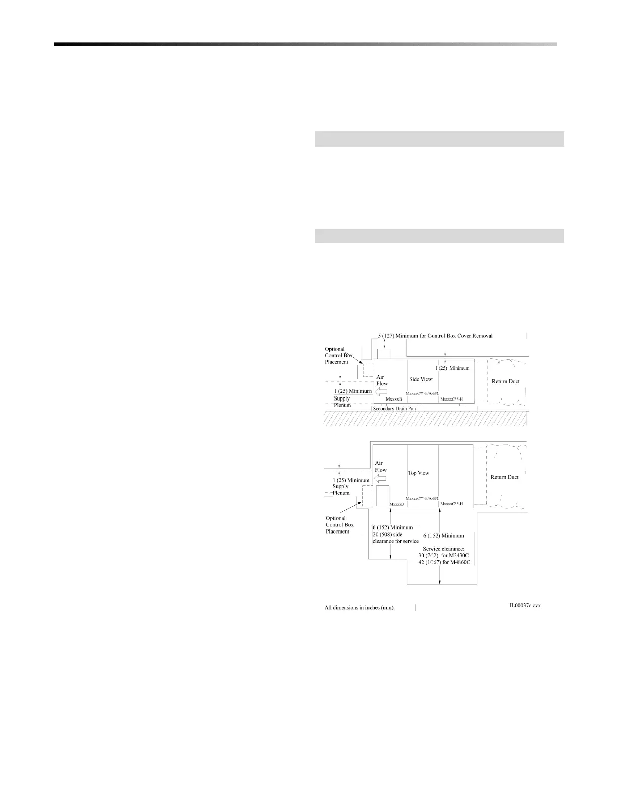
LOCATION
Locate the air handler to minimize the number of
plenum elbows and fittings while keeping the supply
duct runs as short as possible. (See Bulletin 40-030,
Component Duct Layout Design). Provide minimum
clearance on both sides for servicing the unit as shown
in Fig. 1.
Figure 1. Minimum Clearances
 Loading...