Multiple Returns. If more than one return is desired,
Unico has designed a return plenum (MR) module.
The MR module is available in three sizes: 2430, 3036,
and 3642/4860, and it includes a central filter. The MR
module is easily fitted to the air handling unit and
multiple return openings may be cut in the top back or
sides of the box. Refer to Bulletin 20-20.6, Return
Plenum Module, for additional information.
PIPING
All piping must be in accordance with all local codes
and ordinances.
Condensate Lines. The primary drain pan condensate
connection is a ¾-inch (19mm) female pipe thread
fitting, and the secondary drain pan connection is a
¾inch (19mm) PVC socket fitting.
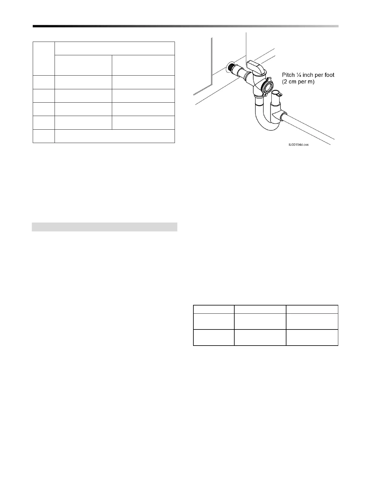
• Elevate the unit so the condensate lines are pitched
at least ¼-inch per lineal foot (20 mm per meter).
• Trap the condensate line near the unit using U-trap
A00924-G05 as shown in Figure 20.
• If located in a high humidity area, above 50°F
(10°C) dew point, insulate the condensate line to
prevent water condensation on the outside of the
pipe.
• In cold climates, protect the trap from freezing in the
winter.
• Do not trap the secondary drain line and do not
terminate connect to the primary drain line.
Figure 20. Typical Condensate Trap
The standard trap that ships with the cooling coil
includes a float switch to shut off the system if the
drain is plugged up.
Run secondary drain line so that any drainage will be
immediately known without causing damage to
property. A typical location is to terminate the
secondary drain line above a windowsill so that the
drainage splashes on the window. This will serve as an
indicator that there is a problem with the primary drain.
In cases where a secondary drain line cannot be run,
add a float switch or a micro switch with a paper fuse.
Refrigerant Connections. All refrigerant coils have
two refrigerant lines: a liquid line (small tube) and a
vapor line (large tube). The connections are either
sweat or flare as listed in table 6, depending on what
type of outdoor unit the cooling module is matched to.
Table 7. Refrigerant Line and Connection Size
Refer to the condensing unit manufacturer’s instruction
for proper line sizing information based on distance
from condenser.
For 1 and 2-stage outdoor units (non-iSERIES), install
a liquid line filter drier as close to the coil module as
possible to protect the evaporator from foreign object
debris. For attic installations or when using long line
sets, an optional moisture indicating sight glass should
also be installed between the filter-drier and expansion
valve, near the indoor unit.
Use the following steps when connecting the
refrigerant lines:
 Loading...