Bulletin 30-020.007
Copyright © 2019 Unico Inc. Page 15
DUCT CONNECTIONS
Supply Plenum (main duct). The main duct (or
plenum) can be round, square or rectangular, provided
it meets the pressure drop requirements of the
application. Adapters are available for the standard
sizes for both round and square ducts.
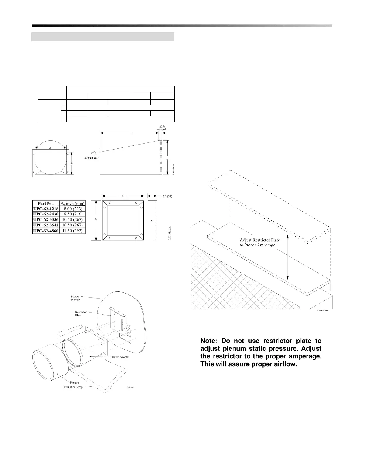
Figure 15. Round Supply Plenum Adapter
Dimensions
Figure 16. Square Supply Plenum Adapters
To attach the plenum adapter, first install the restrictor
plate (for ST only). Then install the adapter with eight
(8) sheet metal screws as shown in Fig. 17. Sheet metal
screws for installing both are provided with the
blower.
Figure 17. Supply Plenum Adapter Installation
Restrictor Plate (ST). The single speed (non-ECM)
blower includes a restrictor plate to fine-tune the
airflow. The purpose of the restrictor plate is to
eliminate objectionable outlet noise because the
blower is delivering more air than required. In some
cases where the maximum airflow is required, the
restrictor may be omitted.
The restrictor plate is used to set the system airflow.
The full open position corresponds to the highest
airflow the installed duct system will allow (figure 18).
Set the restrictor plate to the full open position and
measure the system airflow. The required system
airflow is 200-250 CFM per nominal ton (27-34 L/s
per nominal kW). Measure the motor amperage and
use this to ensure the 200-250 CFM per nominal ton
(27-34 L/s per nominal kW) has been achieved. If
elevated sound levels are noticed at the outlets with
more than 250 CFM per nominal ton (34 L/s per
nominal kW), the airflow may be reduced with the
restrictor plate. Always measure the system airflow by
the motor amperage (see Table 4). Refer to the airflow
amperage charts provided with the blower.
Figure 18. Restrictor Setting (only used with single
speed motor)
 Loading...