Bulletin 30-020.007
Copyright © 2019 Unico Inc. Page 26
Using a Low Ambient Control Kit. Since the Unico
System operates at colder coil temperatures (in cooling
mode), an anti-frost switch is installed on the coil to
prevent coil freeze-up. In certain instances, such as
when the outdoor ambient temperature is low, the
condensing unit will cycle on the anti-frost switch.
This may reduce the cooling capacity at a time when
the cooling load is still fairly high. To provide better
control and comfort, install a low ambient control on
the condensing unit. Typically, a low ambient control
is necessary when operating the unit at outdoor
temperatures below 80°F (26.6 °C), especially for a 5-
ton nominal capacity system.
These controls come in different configurations such as
the Hoffman Controls Corp. series 800AA-head
pressure control. This control modulates the outdoor
fan to maintain a minimum liquid line temperature.
Other controls may cycle the fan on/off. In either case
check with the condensing unit manufacturer to
determine what controls are compatible with the
condensing unit.
MAINTENANCE (1218, 2430, 3036, 3642,
4860)
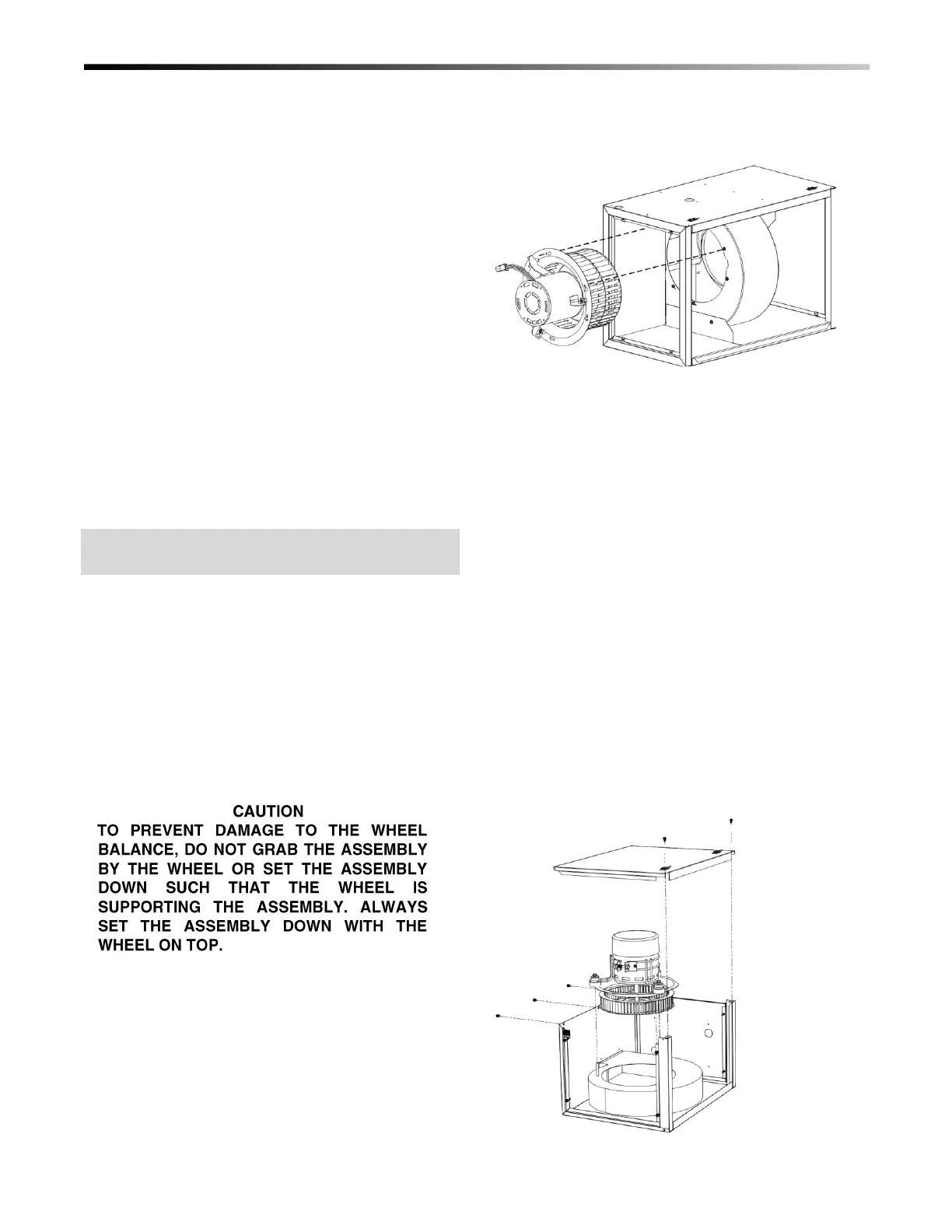
When service is required to the motor or the wheel, the
entire assembly may be removed as a unit (see Figure
34). The blower assembly unit is accessible from the
piping side of the unit. It is not necessary to disconnect
any module or ducting.
To remove the motor and blower wheel assembly,
loosen the six (6) screws fastening the motorized
blower assembly to the blower housing. Twist the
motorized blower assembly counter-clockwise (CCW)
and pull the assembly away from the blower housing.
Once the assembly is removed, the proper service may
be performed. If the wheel is to be changed, it may
simply be removed from the motor shaft by loosening
the motor set screw and pulling the blower wheel off
the motor shaft. If the motor is to be changed, first the
blower wheel must be removed as mentioned above,
and then the screws fastening the motor to the inlet ring
must be removed.
To re-install the motorized blower assembly back into
the blower housing, follow the steps mentioned above
in reverse order. It is not necessary to access both
sides of the unit to remove motor.
Figure 34. Removal of the Motorized Blower
Assembly
Maintenance (1218). To remove the M1218 blower
assembly, loosen and remove the five (5) screws
securing the top blower module plate. Remove the
three (3) nuts, lock washers, and flat washers securing
the blower assembly to the blower wheel housing.
Carefully lift the motor, wheel, inlet ring, and motor
mounting ring off the threaded pins attached to the
blower wheel housing.
If the wheel is to be changed, it may simply be removed
from the motor shaft by loosening the motor set screw
and pulling the blower wheel off the motor shaft. If the
motor is to be changed, first the blower wheel must be
removed as mentioned above, and then loosen the
screw in the motor belly band holding the motor in
place.
To re-install the motorized blower assembly back into
the blower housing, follow the steps mentioned above
in reverse order. It is not necessary to remove the
door panels to remove the motor.
Figure 35. Removal of M1218 Motorized Blower
Assembly
 Loading...