Bulletin 30-020.007
Copyright © 2019 Unico Inc. Page 20
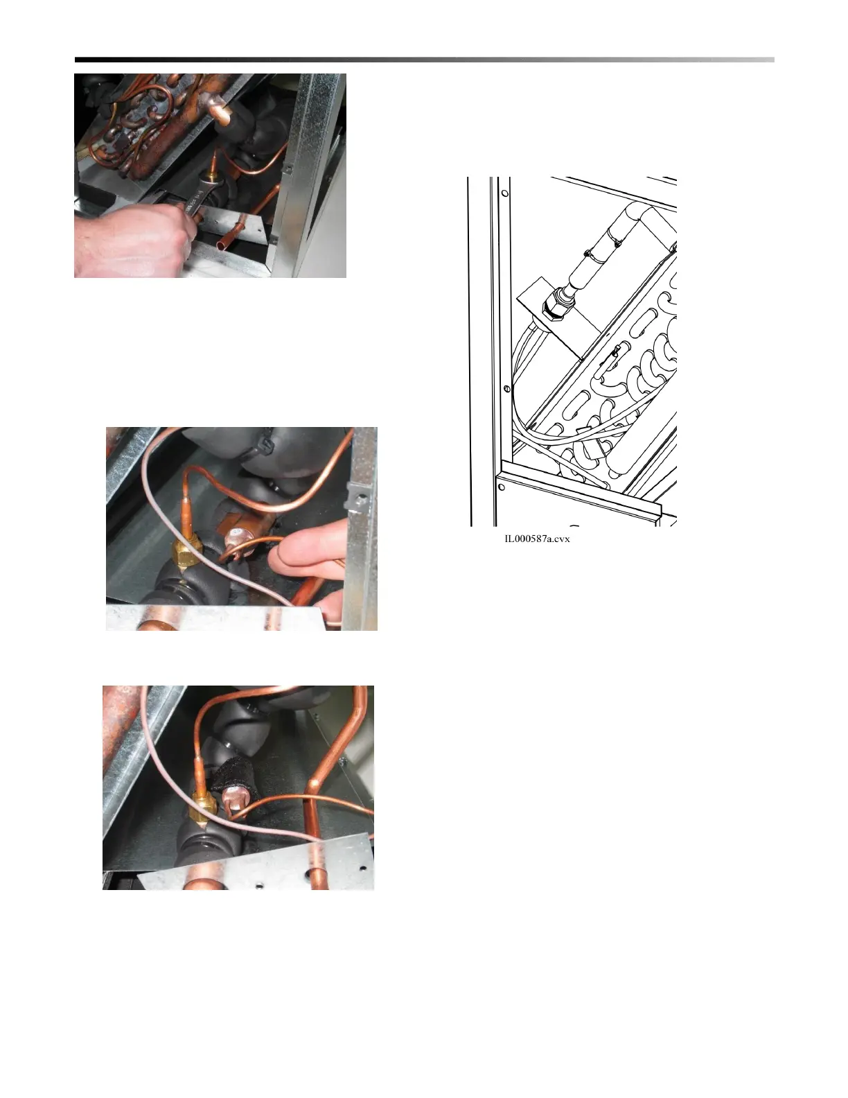
Figure 27. Tighten Pressure Tube Nut
4. Locate the bulb on a horizontal straight section of
the suction line (Figure 28). Attach the bulb to the
tubing with clamp provided and wrap with two
pieces of cork tape (Figure 29). For satisfactory
expansion valve control, good thermal contact
between the bulb and the suction line is essential.
Figure 28. Thermal Measuring Bulb Placed on
Copper Tube.
Figure 29. Bulb Secure Clamp and Cork Tape
5. After all lines have been connected, pressure
check the connections by charging the system
with 150 psig of dry nitrogen and check for leaks
at all connections.
STEP 4 CONNECT SMALL TUBE
(ISERIES ONLY)
For the iSeries coil, connect the small tube directory
to the distributor, where the TXV would normally be
located (Figure 30).
Figure 30. Attach and tighten connection nut
straight to distributor (iSeries coils only)
STEP 5. CONNECT THE LINE SET.
Braze the line sets to the copper stubs or connect to the
flare. If brazing, use a nitrogen purge and protect the
expansion valve by wrapping it with a wet cloth. For
threaded flare fittings, use 1 or 2 drops of refrigerant
oil on the flare (not on the threads) and tighten per the
torque specified in the iSeries manual.
Water Coil Connections. If you are installing the hot
water coil, remove the side coil access panel and cut
away the insulation. Slide the coil into the cabinet and
secure with brackets supplied with the hot water coil.
Install the access panel after the coil is in place.
All water connections are 7/8-inch (22mm) sweat OD
connections. Sweat the water connections, then fill the
system. Bleed the air from the coil by backing off the
screw inside the bleed valve for venting (Fig. 31).
If unit is in an unconditioned space below freezing,
care must be taken not to freeze the water in the coil.
The best method is to use a glycol-water antifreeze
solution with a freezing point below the coldest
temperature expected.
 Loading...