Bulletin 30-020.007
Copyright © 2019 Unico Inc. Page 19
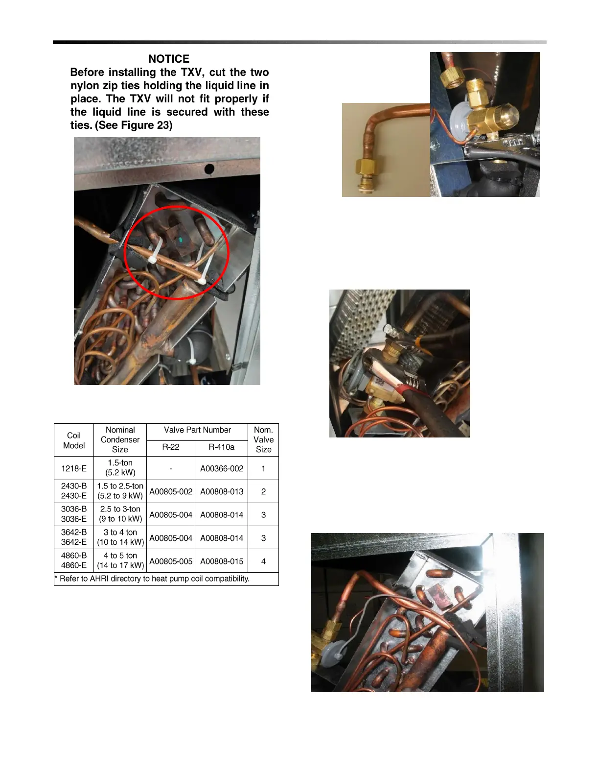
Figure 23. Cut zip ties before installing TXV
Table 8. Expansion Valve model numbers
1. Cut the zip ties holding the liquid line in place before
installing the TXV. Install the white Teflon o-ring
in both connections of the TXV (Figure 24). Attach
and tighten lower connecting nut to the distributor
as shown in Figure 24. On iSERIES, connect liquid
line directly to the distributor (Figure 27).
Figure 24. Install White Teflon O-ring in both
connections (not on iSeries). Attach and tighten
lower connecting nut
2. Connect the outlet to the 3/8" (9.5 mm) OD copper
refrigerant fitting. Make sure the threaded fitting
is tight (Figure 25).
Figure 25. Attach and tighten upper connecting
nut (B/E coils)
3. Route both the external equalizer pressure tube and
the thermostatic bulb tube (Figure 26). Then
tighten the external equalizer line to the flare
connection (Figure 27).
Figure 26. External equalizer line and themostatic
bulb line location routing
 Loading...