UM980 User Manual
16 Hardware Design UC-00-M32 EN R1.1
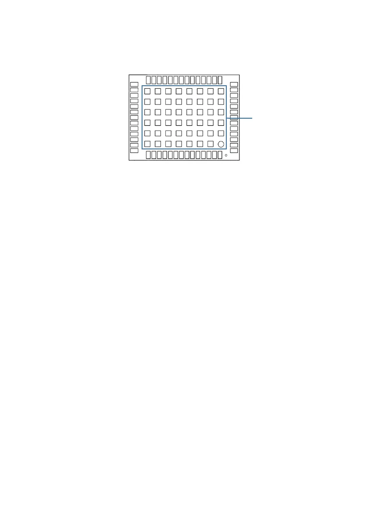
3.3 Grounding and Heat Dissipation
Grounding and
heat dissipation pad
Figure
3-3
Grounding and Heat Dissipation Pad
(Bottom View)
The
48
pads
in the rectangle in Figure 3-3 are for grounding and heat dissipation. In
the PCB design,
the pads should be connected to
a large sized ground to
strengthen
the heat dissipation.
3.4
Power-on and Power-off
VCC
The VCC initial level
when power-on
should be
less than 0.4 V
and
has good
monotonicity.
The voltages of
undershoot and ringing
should be
within 5% VCC.
VCC
power-on waveform: The time interval from 10% rising to 90% must be within 100
us ~1 ms.
Power-on time
interval:
The time
interval between the VCC < 0.4 V (after power-off) to
the next power-on must be larger than 500 ms.
V_BCKP
The V_BCKP
initial level
when power-on should be
less than 0.4 V
and
has good
monotonicity. The voltages of
undershoot and ringing
should be within 5%
V_BCKP.
V_BCKP power-on waveform: The time interval from 10% rising to 90% must be within
100 us ~1 ms.
Power-on time
interval:
The
time
interval between the V_BCKP
< 0.4 V (after power-off)
to the next power-on must be larger than 500 ms.