Control Room Unit for Model 9100 Carbon Monoxide Monitors User Guide
4
Location, Assembly and Installation Instructions
Do NOT install the control room unit where there is
conductive dust, corrosive or ammable gas, moisture or rain, excessive heat and
shocks or excess vibration
Do not allow debris to fall inside the unit during installation.
Leave 10 mm space for ventilation between the top and bottom edges of the controller
and the enclosure wall.
Where panel is mounted on a metal plate, earth the power supply.
Connecting the Control Room Unit to the Carbon Monoxide Monitor
The common connection should be connected as shield to the 0 V terminal of the
control room unit.
A two pin connector is supplied with the control room unit. Connect to port COM3 of
the control room unit.
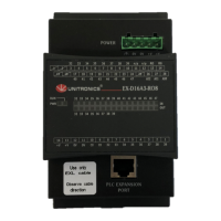
The Control Room Unit is connected directly to the Model 9100 receiver.
Direct Connection to Transceiver
Connect the COM3 port on the CRU to Connector C on the Model 9100 receiver using
the small connector supplied with the CRU.
RS485
Function
CRU Connector
Pin
CRU Connector
Color
Receiver
Connector Pin
Receiver Cable
Colour
D1 (B) 1 Red A, D Black, White
D0 (A) 6 White B, C Brown, Red