CAT-5e shielded cable with RJ45 connector
Use the proprietary programming cable supplied with the device
Standard USB cable with Type-A plug
Use 3.5mm stereo audio plug with shielded audio cable
Note that only Pro models support this feature.
Audio Pinout
Headphone Right Out (Ring)
Note that below, the letter “x” that is used in the model numbers means that the section
refers both to B5 and B10 models.
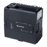
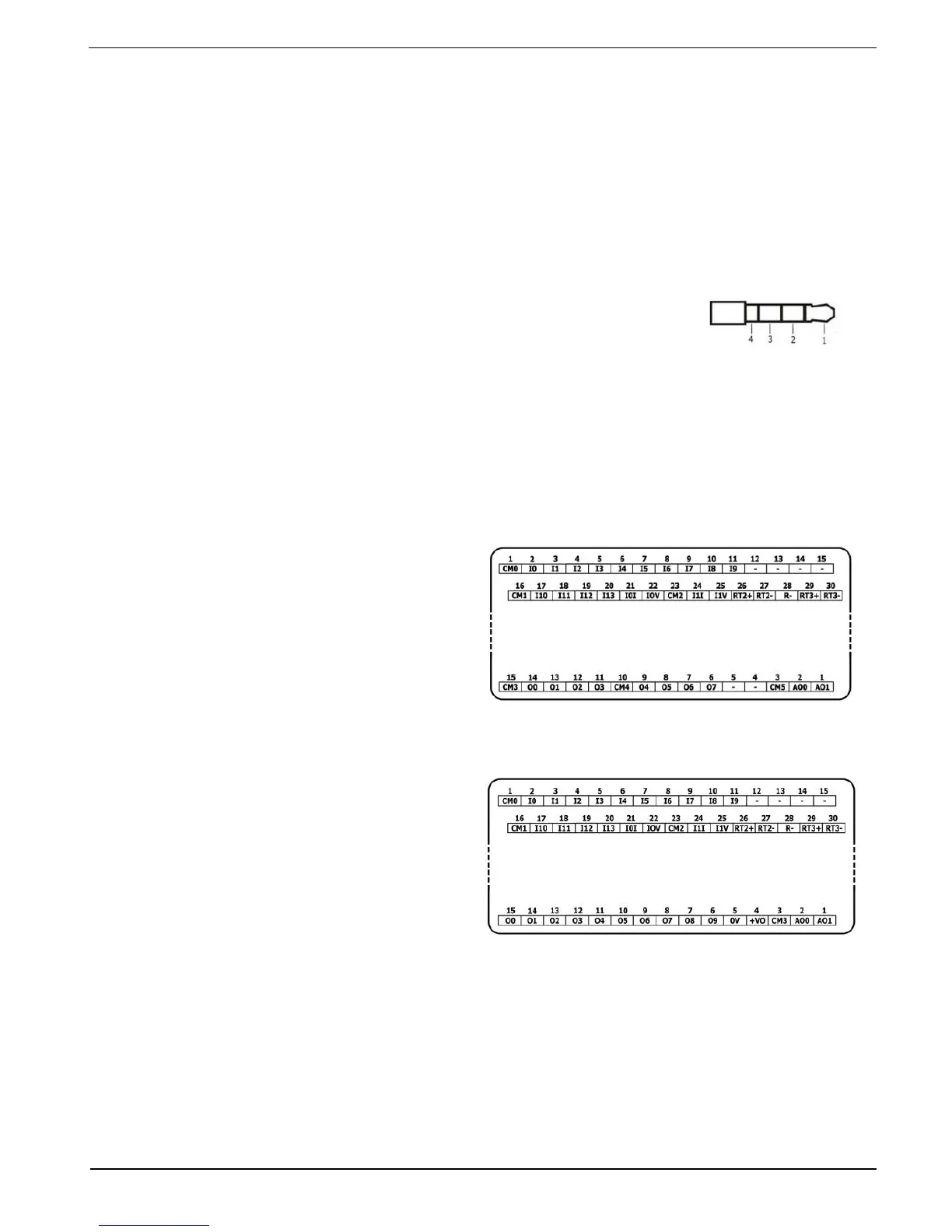
I/O Connection Points
All IO wiring diagrams and instructions in
this section refer to the US5-Bx-RA28 and
US5-Bx-TA30 connection points. These
are arranged in three groups of fifteen
points each, as shown in the figures to
the right.
Top groups
Input connection points
Bottom group
Output connection points
The function of certain I/Os may be
adapted via wiring and software settings.
Wiring the Digital Inputs
The digital inputs are arranged in two isolated groups:
I0-I9 share common CM0
I10-I13 share common CM1
Each group may be wired together as sink or source.
Inputs I10, I11, I12 and I13 can be configured as either normal digital inputs or as high
speed inputs that can receive high speed pulse signals from sensors or shaft encoders.