17
Interconnection Diagrams
Analog-Only Setup
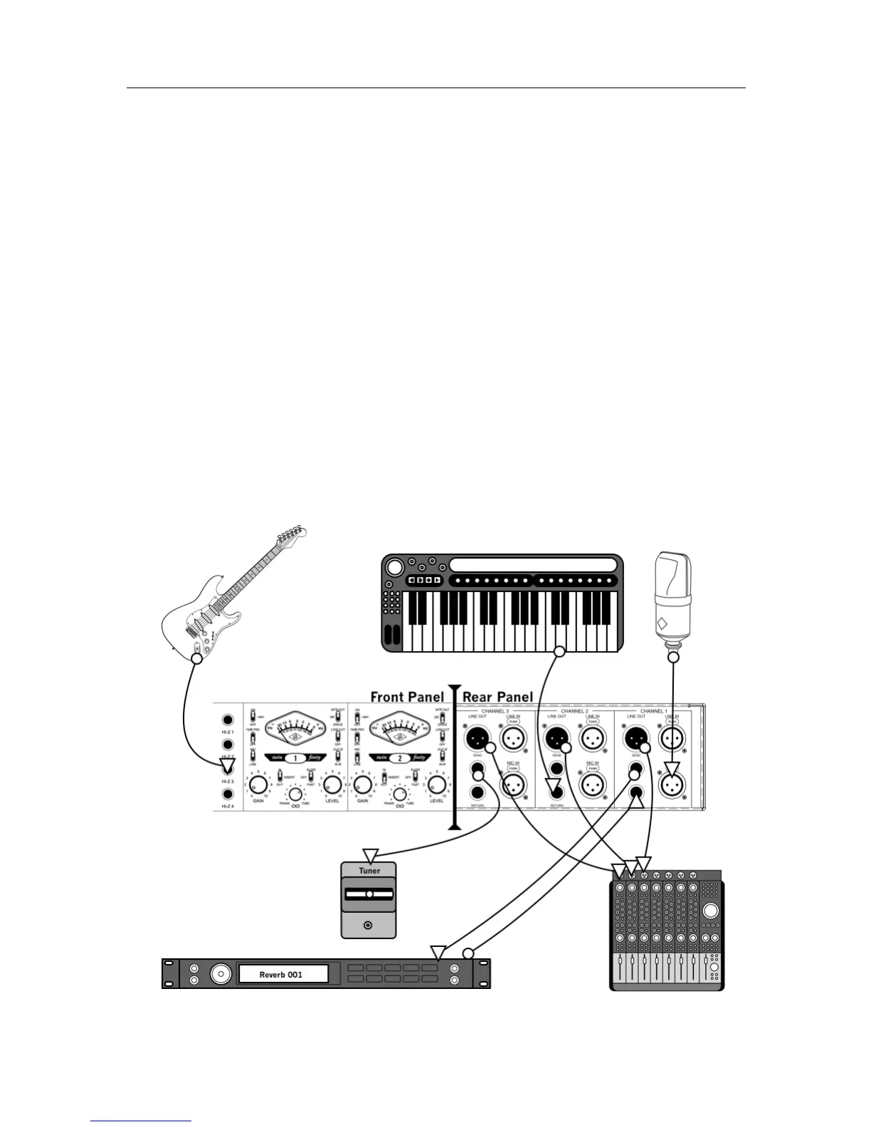
This diagram illustrates a typical system using the 4-710d in an analog-only configuration, such as
when using it as the front end to a public address system or analog recording device. In this setup, the
digital features of the 4-710d are not used.
The example shows a microphone connected to channel 1, a keyboard connected to the insert return of
channel 2 (to use the ¼” line input instead the XLR line input), and a guitar connected to channel 3
using the Hi-Z input. A signal processor (e.g., reverb) is connected via the insert loop of channel 1 for
the mic. The insert send of channel 3 (but not the return) is used as a guitar direct output for
connection to a tuner. The line outputs are connected to an analog mixer where the input signals are
combined before being sent to powered PA speakers.
Key points for this example:
• Mic/Line switch for channel 1 is set to “Mic”
• Insert switches for channels 1 and 2 are set to “In”
• Line outputs are connected to an analog mixer for monitoring