Apollo x4 Hardware Manual Controls & Connectors 28
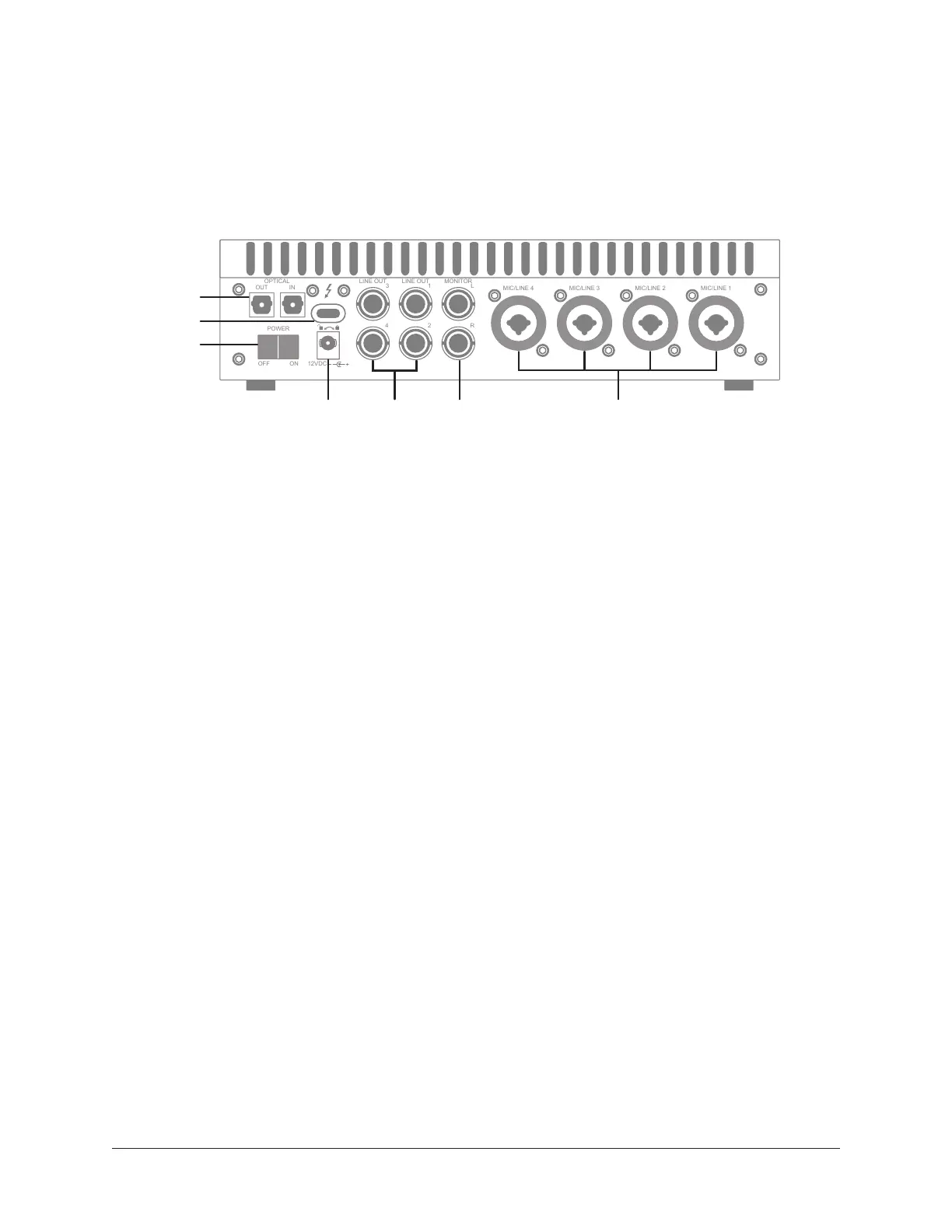
Rear Panel
Refer to the illustration below for numbered control descriptions in this section.
Note: All rear panel ¼” jacks can accept unbalanced TS (tip-sleeve) or balanced
TRS (tip-ring-sleeve) plugs.
Rear panel elements
(15) Mic/Line Combo Inputs
The jacks for preamp channels 1 – 4 accept either a male XLR plug for connecting to the
mic input, or a ¼” phone plug for connecting to the line input.
The input jack that is used for the preamp channel (mic or line) is specified with the
Input Select button (8-a).
Caution: To avoid potential equipment damage, disable +48V phantom power on
the channel before connecting or disconnecting its XLR input.
(16) Monitor Outputs
Connect the powered monitor speakers (or speaker system amplifier inputs) here. Volume
is controlled with the Level knob (1) when MONITOR is selected (8) with the MONITOR
button (12). The Monitor Outputs are DC coupled.
(17) Line Outputs 3 – 6
These ¼” phone outputs are accessed via software (Console or DAW). Line outputs 3 – 6
are typically used to send audio to other equipment. The Line Outputs are DC coupled.
OPTICAL
OUT IN
OFF ON
12VDC
POWER
1
2 R
LINE OUT MONITOR
3
4
LINE OUT
MIC/LINE 4 MIC/LINE 3 MIC/LINE 2 MIC/LINE 1
L
OPTICAL
OUT IN
OFF ON
12VDC
POWER
1
2 R
LINE OUT MONITOR
3
4
LINE OUT
MIC/LINE 4 MIC/LINE 3 MIC/LINE 2 MIC/LINE 1
L
a b c d e f
g h i j k l
43
8
7
12
5
6
9 10 11
161718
21
20
19