I
vOIIS.1
+ -
BlK
RED
FIELD
RHEOSTAT
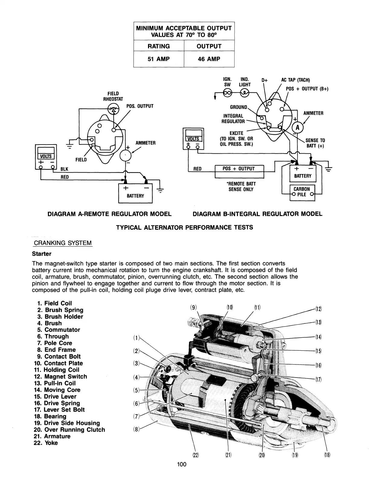
MINIMUM ACCEPTABLE OUTPUT
BATTERY
VAWES
AT
70°
TO
80°
RATING
OUTPUT
51
AMP
46
AMP
RED
INTEGRAL
REGULATOR
EXCITE
(TO
IGN.
SW.
OR
Oil
PRESS.
SW.)
POS
+
OUTPUT
"REMOTE
BATT
SENSE
ONLY
0+
AC
TAP
(TACH)
DIAGRAM A-REMOTE REGULATOR MODEL DIAGRAM B-INTEGRAL REGULATOR MODEL
CRANKING
SYSTEM
Starter
TYPICAL ALTERNATOR PERFORMANCE TESTS
The magnet-switch type starter is composed of two main sections. The first section converts
battery current into
mechanical rotation to turn the engine crankshaft. It is composed of the field
coil,
armature, brush, commutator, pinion, overrunning clutch,
etc.
The second section allows the
pinion and
flywheel to engage together and current to flow through the motor section. It is
composed of the
pull-in coil, holding coil pluge drive
lever,
contract plate,
etc.
1.
Field Coil
2. Brush Spring
3.
Brush
Holder
4.
Brush
5.
Commutator
6.
Through
7.
Pole Core
8.
End Frame
9.
Contact
Bolt
10.
Contact Plate
11.
Holding Coil
12. Magnet
Switch
13.
Pull-in Coil
14.
Moving Core
15.
Drive Lever
16.
Drive Spring
17.
Lever Set
Bolt
18.
Bearing
19.
Drive Side Housing
20. Over Running Clutch
21.
Armature
22. Yoke
100