ENGINE
COOLING
CIRCUIT
Changing
the
Raw
Water
Impeller
1. Close the raw water intake,
2. Remove the inlet and outlet
rx>rt
hoses from the pump,
noting the port location and positioning.
3. Remove the pump assembly and its gasket from the
engine.
4. Remove the three hex head
screws
that hold the housing
to the cover.
5. Tap
the
housing/cover assembly on its side to loosen and
separate the cover from its housing.
6. Remove the cover and its
O-ring and remove
the
impeller
gasket and plate.
7. Remove the retaining ring (circ1ip) and
pry
out the
impeller. Take care not to lose the key
off
the shaft's key-
way.
ACAUTION:
If
any
of
the
vanes
have
broken
off
the
impeller
they
must
be
found
to
prevent
blockage
in
the
cooling
circuit.
They
often
can
be
found
in
the
heat
exchanger.
8. Replace the gasket, impeller, and O-ring.
9. Apply a film
of
petroleum jelly
or
silicone
to
the inner
surface
of
the impeller housing.
NOTE:
Just coat the surface, do not over apply.
10. Install the
cover
housing
over
impeller.
11. Install the three hex
screws
and tighten.
15
12. Mount the pump to the engine taking care thai the end
seal and gasket are
in
place.
Do
not tighten the pump
mounting screws, just finger tight.
13.
Rca<;semhlc the hose connections and open the raw
water
intake.
14.
Start the engine
in
idle, this will allow the
pump
to align
itself with its drive shaft.
15.
Stop
the engine and tighten the
pump
assembly mount-
ing screws.
16.
Start and run the engine, check for leaks and check for a
norrnal operating temperature.
NOTE:
Should a failure occur with the pumps internal parts
(seals and bearings)
it
may be more cost efficient
to
purchase
a new pump. The price
of
individual parts would almost
match the price
of
a new pump.
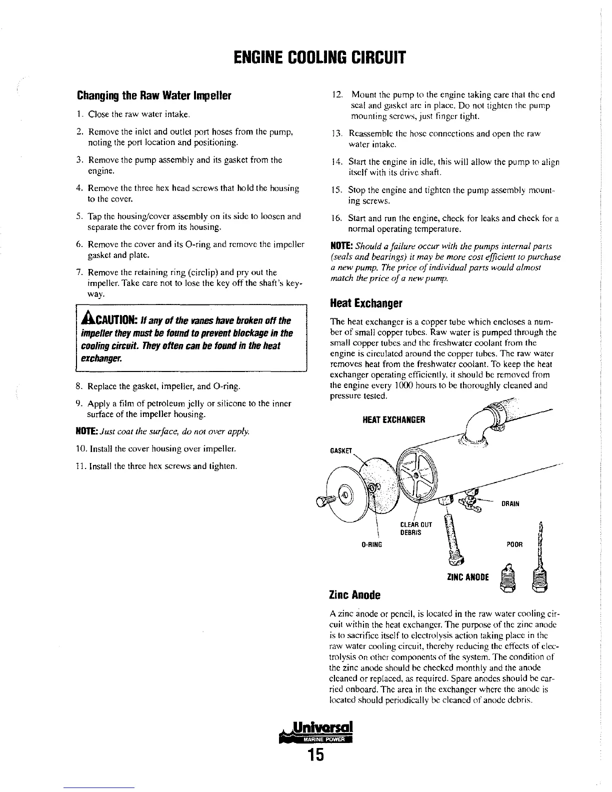
Heat
Exchanger
The
heat exchanger is a copper
tUhe
which encloses a num-
ber
of
small copper tubes. Raw water is pumped through the
small
copper
tubes and the freshwater coolant from the
engine is circulated around the
copper
tubes.
The
raw water
removes heat from the freshwater coolant. To keep the heat
exchanger operating efficiently,
it
should be removed from
the engine every 1000 hours to be thoroughly cleaned and
pressure tested.
HEAT
EXCHANGER
O-RING
Zinc
Anode
CLEAR
OUT
DEBRIS
DRAIN
POOR
ZINC
ANODE
i
A zinc anode
or
pencil, is located
in
the raw water cooling cir-
cuit within the heat
exchanger.
The
purpose
of
the zinc anode
is
to sacrifice itself to electrolysis action taking place
in
the
raw water cooling circuit, therehy reducing the effects
of
elec-
trolysis
on
other components
of
the system.
The
condition
of
the zinc anode should be checked monthly and the anode
cleaned
or
replaced,
a<;
required. Spare anodes should he car-
ried onboard.
The
area in the exchanger where the anode
is
located should periodically he cleaned
of
anode dehris.