DC
ELECTRICAL
SYSTEM
ENGINE
12
VOLT
DC
CONTROL
CIRCUIT
The engine has a
12
volt
DC
electrical control circuit that
is
shown on the wiring diagrams that follow. Refer to these dia-
grams when troubleshooting or when servicing the
DC
elec-
trical system on the engine.
DRIVE
BELT
ADJUSTMENT
A
CAUTION:
Drive
belts
must
be
properly
tensioned.
Loose
drive
belts will not
provide
proper
alternator
charging
and
will
eventually
damage
the
alternator.
Drive
belts that
are
too
tight will pull
the
alternator
out
of
alignment
and/or
cause
the
alternator
to
wear
out
prematurely.
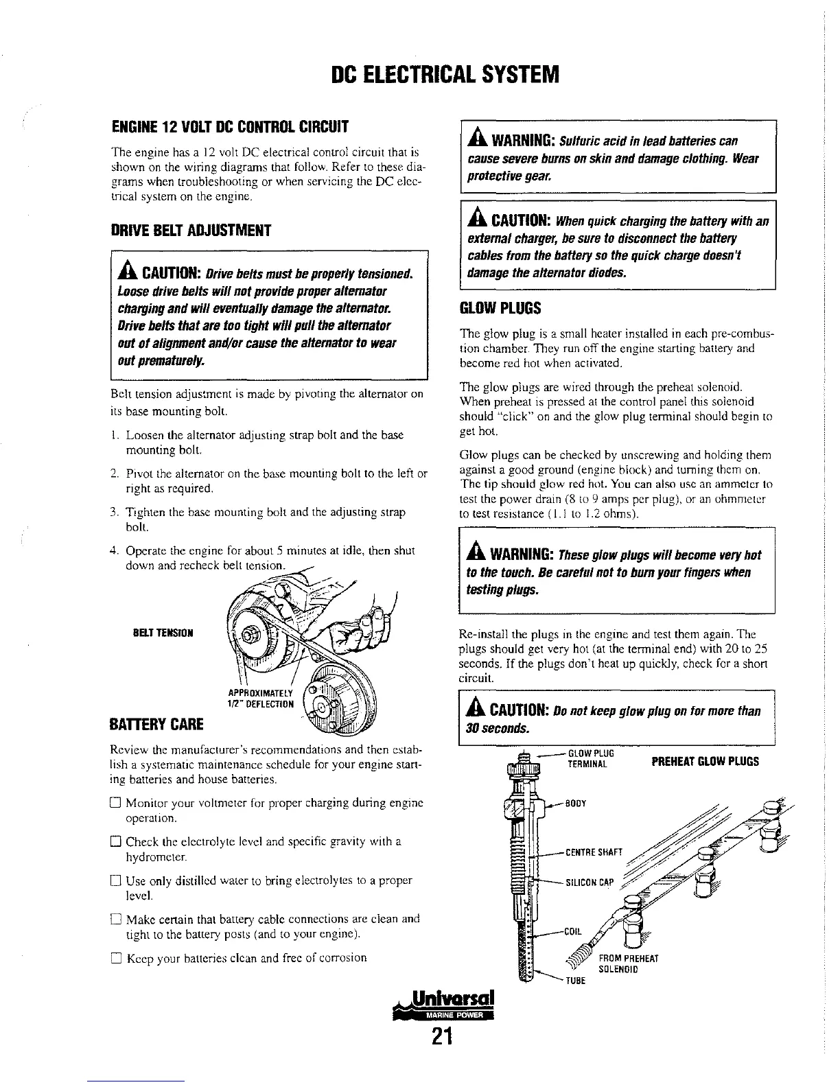
Belt tension adjustment
is
made by pivoting the alternator
on
its base mounting bolt.
1.
Loosen the alternator adjusting strap bolt and the base
mounting
bolt
2.
Pivot
the
alternator on the base mounting bolt to the left or
right
as
required.
3.
Tighten the base mounting bolt and
the
adjusting strap
bolL
4.
Operate the engine for about 5 minutes at idle, then shut
down and recheck belt tension.
BElT
TENSION
BATTERY
CARE
Review the manufacturer's recommendations and then estab-
lish a systematic maintenance schedule
for
your engine start-
ing batteries and house batteries.
o Monitor your voltmeter for proper charging during engine
operation.
o Check the electrolyte level and specific gravity with a
hydrometer.
o Use only distilled water
to
bring electrolytes
to
a proper
lcvel.
o Make certain that battery cable connections are clean and
tight
to the battery posts (and
to
your engine).
o Keep your batteries clean and free of corrosion
21
A
WARNING:
Sulfuric
acid
in
lead
batteries
can
cause
severe
burns
on
skin
and
damage
clothing.
Wear
protective
gear.
A
CAUTION:
When
quick
charging
the
battery
with
an
external
charger,
be
sure
to
disconnect
the
battery
cables
from
the
battery
so
the
quick
charge
doesn't
damage
the
alternator
diodes.
GLOW
PLUGS
The glow plug
is
a small heater installed
in
each pre-combus-
tion chamber. They run off the engine starting
bauery and
become red hot when activated.
The glow plugs are wired through the preheat solenoid.
When
preheat
is
pressed at the control panel this solenoid
should
"click" on and the glow plug terminal should begin
to
get hal.
Glow plugs
can
be checked by unscrewing and holding them
against a good ground (engine block) and turning them on.
The
tip should glow red hot. You can also usc an ammeter to
test the power drain
(8
to
9 amps per plug), or an ohmmeter
to test resistance
(I.!
to
1.2
ohms).
A
WARNING:
These
glow
plugs
will
become
very
hot
to
the
touch.
Be
careful not
to
burn
your
fingers
when
testing
plugs.
Re-install the plugs
in
the engine and test them again. The
plugs should get very hot (at the terminal end) with
20
to
25
seconds. If the plugs
don't
heat up quickly, check
for
a short
circuit.
A
CAUTION:
Do
not
keep
glow
plug
on
for
more
than
30
seconds.
_GLOW
PLUG
TERMINAL
PREHEAT
GLOW
PLUGS
~~.
CENTRE
SHAFT
~
;;;:;'
""'
J
SILICON
CAP
y/""
-'"'
---
TUBE
FROM
PREHEAT
SOLENOID