3
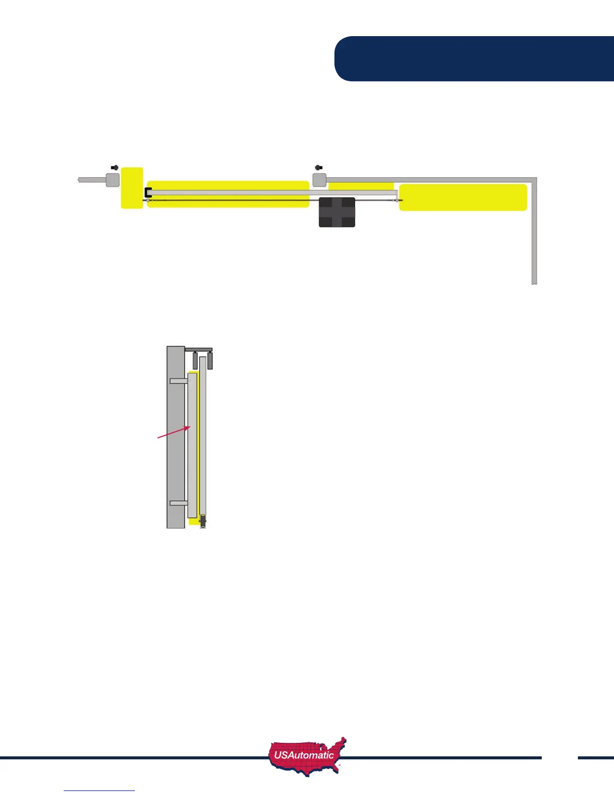
The illustrations below are a guide to help identify entrapment areas for slide gate installations that must
be protected. Other entrapment areas may exist and must be identied by the installer and protected by
the appropriate monitored entrapment protection device for the situation.
Zone 1 - Leading edge of gate where it meets a stop
post, 2nd gate or other immovable object.
Recommended monitored entrapment protection
type B2 wireless contact sensor.
Zone 2 - A gap, measured in the horizontal plane parallel
to the roadway, between a xed stationary object
nearest the roadway (such as a gate support post)
and the gate frame when the gate is in either the
fully open position or the fully closed position, shall
not exceed 2 1⁄4 in. (57 mm).
Exception: All other xed stationary objects
greater than 16 in. (406 mm) from the gate frame
shall not be required to comply with this section.
Zone 3 - The path the gate travels. Recommended
monitored entrapment protection type B2
wireless contact sensor.
Zone 4 - Gate opens toward an immoveable object with
less than 16 inches of clearance - recommended
monitored entrapment protection type B1 photo
eye or equivalent. If space is less than 16”,
entrapment protection in this area is required.
(ASTM F2200: 7.1.1.1 and 7.1.1.2)
ENTRAPMENT ZONES
1.
4.
2.3.
2.
Panel to ll in
cavity greater
than 2 1/4”
(57mm)


 To Next Page