EasyManua.ls Logo

USAutomatic Ranger HD User Manual

USAutomatic Ranger HD
60 pages
To Next Page IconTo Next Page
Page #1 background imageLoading...
Page #1 background image
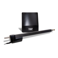
Heavy Duty Battery Powered Solar or AC Charged
Ranger
®
Swing Gate Operators
16 Inch Stroke
Ranger
®
HD
Swing Gate Operator
24 Inch Stroke
Installation/Owners Manual
www.USAutomaticGateOpeners.com | (800) 878-7829 | Sales@USAutomaticGateOpeners.com

Table of Contents

Questions and Answers:

USAutomatic Ranger HD Specifications

General IconGeneral
BrandUSAutomatic
ModelRanger HD
CategoryGate Opener
LanguageEnglish

Summary

RANGER Series AUTOMATIC GATE OPERATORS

Class I Residential Gate Operator Definition

Defines Class I gate operator for single-family residences.

Class II Commercial Gate Operator Definition

Defines Class II gate operator for commercial/public locations.

Class III Industrial Gate Operator Definition

Defines Class III gate operator for industrial locations.

Class IV Restricted Gate Operator Definition

Defines Class IV gate operator for guarded/restricted locations.

Solar Friendly Design Benefits

Explains solar-friendly design and benefits.

Battery Requirements and Installation

Details recommended battery type and installation caution.

Entrapment Devices Required and Approved for Operation

Type B1 Non-Contact Sensor Details

Defines Type B1 sensor as photoelectric with N/C contact.

Type B2 Contact Sensor Details

Defines Type B2 sensor as contact edge with 10K resistor.

Type D Actuating Device Details

Defines Type D as constant pressure device.

Approved Wired Contact Edge Devices

Lists approved wired contact edge devices.

Approved Wireless Contact Edge Devices

Lists approved wireless contact edge devices.

Approved Non-Contact Sensors (Type B1)

Lists approved non-contact sensors.

ENTRAPMENT ZONES

Entrapment Zone A: Leading Edge Safety

Defines Zone A entrapment area and recommended device.

Entrapment Zone B: Immovable Object Safety

Defines Zone B entrapment area and recommended device.

Entrapment Zone C: Hinge Point Safety

Defines Zone C entrapment area and recommended device.

Entrapment Zone D: Gate Bottom Edge Safety

Defines Zone D entrapment area and recommended device.

IMPORTANT SAFETY INSTRUCTIONS

SAFETY INSTALLATION INFORMATION

Installing Non-Contact Sensors (Type B1)

Installation guidelines for Type B1 photo eyes.

Installing Contact Sensors (Type B2)

Installation guidelines for Type B2 contact edges.

Installing Constant Pressure Devices (Type D)

Installation guidelines for Type D constant pressure devices.

PARTS INVENTORY

Control Board and Cabinet Components

Lists components included with the cabinet and control board.

2 Button Transmitter Part

Details the 2-button transmitter part.

Solar Panel Kit Part

Details the solar panel kit part.

Safety Signs Part

Details the safety signs part.

Photo Eyes Part

Details the photo eyes part.

DC Adapter Part

Details the DC adapter part.

Ranger HD Actuator Part

Details the Ranger HD actuator part.

Pro80 Ranger Actuator Part

Details the Pro80 Ranger actuator part.

Dual Gate Extension Cable Part

Details the dual gate actuator extension cable.

4 Button Transmitter Part

Details the 4-button transmitter part.

Push to Operate Button Part

Details the push-to-operate button part.

Plastic Wireless Keypad Part

Details the plastic wireless keypad part.

Metal Wireless Keypad Part

Details the metal wireless keypad part.

12/24 Vdc Receiver Part

Details the 12/24 Vdc receiver part.

Electric Gate Lock Part

Details the electric gate lock part.

7 Day Timer Part

Details the 7-day timer part.

Exit Sensor Part

Details the exit sensor part.

Photo Eye Part

Details the photo eye part.

Metal Photo Eye Part

Details the metal photo eye part.

HARDWARE INVENTORY

Support Bracket Hardware

Details the support bracket part.

Mounting Tube Hardware

Details the mounting tube part.

Gate Bracket Hardware

Details the gate bracket part.

Manual Release Pin Hardware

Details the manual release pin part.

Manual Release Pin Clip Hardware

Details the manual release pin clip part.

Nylon Washers Hardware

Details the nylon washers part.

Warning Label Hardware

Details the warning label part.

Bronze Bushing Hardware

Details the bronze bushing part.

3/8" Bolt Hardware

Details the 3/8" bolt part.

3/8" SAE Flat Washers Hardware

Details the 3/8" SAE flat washers part.

3/8" Lock Nuts Hardware

Details the 3/8" lock nuts part.

Threaded Cable Strain Relief Conn. Hardware

Details the threaded cable strain relief connector.

#12 Self Tapping Hex Screw Hardware

Details the #12 self tapping hex screw part.

GENERAL TOOL REQUIREMENTS

ACTUATOR DIMENSIONS

Ranger HD Actuator Dimensions

Provides dimensional specifications for the Ranger HD actuator.

Pro 80 Actuator Dimensions

Provides dimensional specifications for the Pro 80 actuator.

BOX DIMENSIONS

GATE QUALIFICATIONS AND APPLICATIONS

PROPER GATE DESIGN

Mounting Site Review

Determine Opening Method

Determine Horizontal Mounting Location

Mounting Brackets - PULL TO OPEN

Mounting Brackets - PUSH TO OPEN

Mounting Brackets - COLUMNS

Mount Support Bracket

Install Actuator Mounting Tube - PULL TO OPEN

Install Actuator Mounting Tube - PUSH TO OPEN

Install Linear Actuator to Mounting Bracket

Install Gate Bracket to Linear Actuator

Install Gate Bracket to Gate

Install Control Box and Actuator Cable

Splicing Actuator Cable / Dual Gate System

Installing Monitored Entrapment Protection Devices

Monitored Photo Eye (Type B1) Installation

Wiring and dipswitch settings for Type B1 photo eyes.

Monitored Contact Edge (Type B2) Installation

Wiring for Type B2 monitored contact edge devices.

Constant Pressure (Type D) Installation

Wiring for Type D constant pressure operation.

Install Wiring Harness and Battery

Install Battery Controller Power Source

AC Charged System Installation

Details installation for AC powered systems.

Solar Charged System Installation

Connect Power Source to Battery Controller

Install Safety Signs

Connect Linear Actuator Cable to Control Board

Photo Eye Alignment

Operating Gate for the First time

Limit Adjustments

PWM Adaptive Soft Start / Stop Speed Control

Sensitivity, Entrapment Alarm & Auto Close Settings

Verifying Inherent Entrapment Protection (Type A)

Verifying Monitored Photo Eye (Type B1)

Verifying Monitored Contact Edge (Type B2)

Verifying Constant Pressure (Type D) Operation

Ranger Control Board Information

J2 Terminal Description

SWI Function Dip Switches

Programming Transmitter and Receiver

Programming Your Wireless Keypad

Changing Keypad Security Code

Receiver Programming - Hold Gate Open

Emergency Manual Release

PERIODIC SERVICE

Accessories

Electric Gate Lock Accessory

Details the electric gate lock accessory.

Magnetic Gate Lock Accessory

Details the magnetic gate lock accessory.

Exit Sensor Accessory

Details the exit sensor accessory.

Push to Operate Wireless Button

2 Button LCR Transmitter

4 Button LCR Transmitter

12/24 Vdc Receiver AC/DC

Charge Cable Extension Pigtails

Monitored Entrapment Device Expansion Module

7 Day Timer

20 Watt Solar Panel

Troubleshooting Guide

Troubleshooting Guide Introduction

Overview of troubleshooting features on the control board.

Terms and Definitions

Summary of Symptoms

IMPORTANT FIRST STEP

Single Gate Will Not Operate (Ranger I)

Dual Gate Will Not Operate (Ranger II)

Gate Not Operating with Monitored Entrapment Devices

Gate Will Not Automatically Close

Gate Stops and Reverses Intermittently

Single Gate Reverses Immediately

Dual Gate Reverses Immediately

Transmitter Will Not Operate Gate

Transmitter Opens, Won't Close Gate

Photo-Eye Fails to Reverse/Hold Gate

Reset Button Only Operates Gate

Battery Not Staying Charged

Wiring Harness Fuse Blows

Appendix

USAutomatic Battery Controller Details

Details features, specifications, installation, and diagnostics.

Photo Eye - Vehicular Protection

Installing Photo Eye - NOT MONITORED

Installing APP Receiver

Extending Charge Device Location

LIMITED WARRANTY

Related product manuals