EasyManua.ls Logo

USR IOT USR-G781 - LED Indicator; Module Default Parameters

USR IOT USR-G781
29 pages
Print Icon
To Next Page IconTo Next Page
To Previous Page IconTo Previous Page
Loading...
USR-G781 User Manual Technical Support: h.usriot.com
Jinan USR IOT Technology Limited www.usriot.com
8
Interface
Information
LTE antenna
Stick antenna and sucker antenna for chosen
Reload button
Press button for 3~15s to reload to factory settings
Ethernet port
WAN/LAN port can be switch by serial command
Power supply
DC 9~36V power supply
RS232 DB9
female
5 wires RS232(TXD/RXD/GND/RTS/CTS)
RS485 terminal
3 wires RS485: A+/B-/GND
SIM card socket
Insert SIM card here
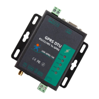
Figure 6 Interface information
1.1.4.LED Indicator
Indicator
Status
Power
On: Power on
Off: Power off
NET
Red: 2G network
Blue: 3G network
Purple: 4G network
Off: No network
WORK
On: Working
Off: Not working
SIM
On: SIM card detected
Off: SIM card not detected
LINKA
On: Socket A connected
Off: Socket A disconnected
LINKB
On: Socket B connected
Off: Socket B disconnected
TXD
On: Sending data to serial
Off: No data sending to serial
RXD
On: Receiving data from serial
Off: No data receiving from serial
Figure 7 Hardware Indicator
1.2. Module Default Parameters
Work mode
Transparent mode
Server Address
test.usr.cn
Server Port
2317
Serial Parameters
115200,8,1,None
Heartbeat packet
www.usr.cn
Figure 8 Default parameters

Related product manuals