Configuring the WIU-4 13
J9: Reserved
The 2-pin connector, J9, is reserved.
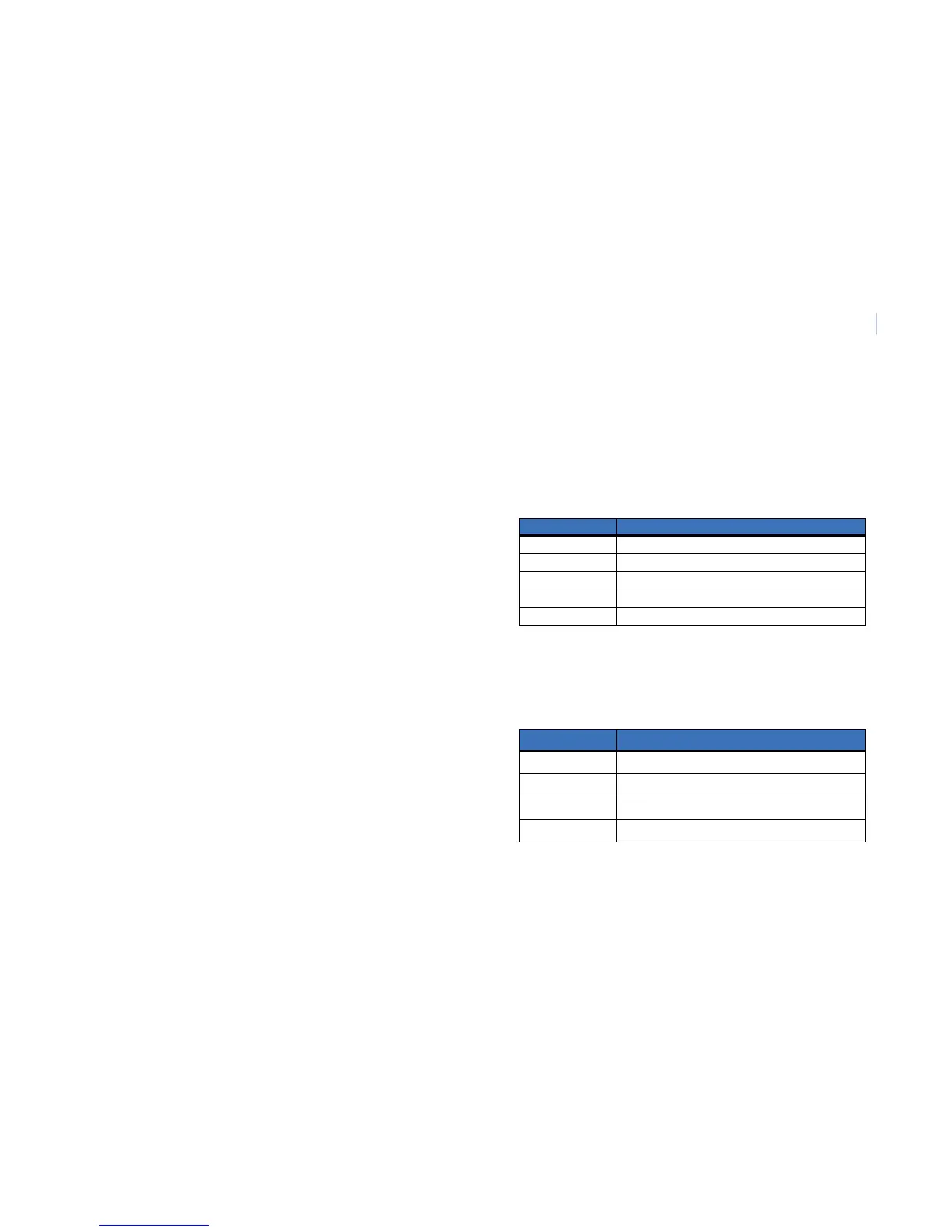
J10: Door strike relay connectors
The 5-pin connector, J10, is the door strike relay
connection.
LED indicators
The four green LEDs on the board provide visual indication
of the system interfaces.
Refer to
“Indicators” on page 17 for LED status indicators and
definitions
Table 5. J10 Door strike relay connector
PIN Description
1 Relay power (Source)
2 Relay power (Return)
3 Normally closed (NC) contact
4 Not used
5 Normally open (NO) contact
Table 6. LED indicators
LED Description
D1 DI monitor LED
D2 F/2F data LED
D3 Door DO LED
D20 Power LED