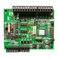
Testing the WIU-4 17
Testing the WIU-4
1. Verify reader (J6), door/REX (J3), door strike (J10),
and micro (J8) connections are properly wired.
2. If the tamper connections on connector J6 are not
used, pin 8, Tamper Select, and pin 9, Tamper
Common, must be connected together. Otherwise,
tamper alarms will be generated.
3. Refer to the
Table 7 to verify proper operation.
4. If the reader does not function, be sure to install a
jumper across pins 1 and 2 of J5.
Indicators
The WIU-4 has four green LEDs that operate as indicated
in the following table.
Table 7. Green LED indicator status
LED Operation
D1 DI Monitor LED
ON = door switch is reporting that the door is closed.
OFF = door switch is reporting the door is open.
The LED works the same regardless of whether the switch is
supervised or not.
D2 F/2F Data LED
Pulses ON for a short time, approximately every 3 seconds,
indicating that the WIU-4 is sending “I’m alive” messages on
the F/2F data output. It also pulses ON once for every badge
read and once for a DI status change.
D3 Door DO LED
ON = Door DO output from the micro is active.
D20 Power LED
ON = board has 12 VDC power connected.

 Loading...