20
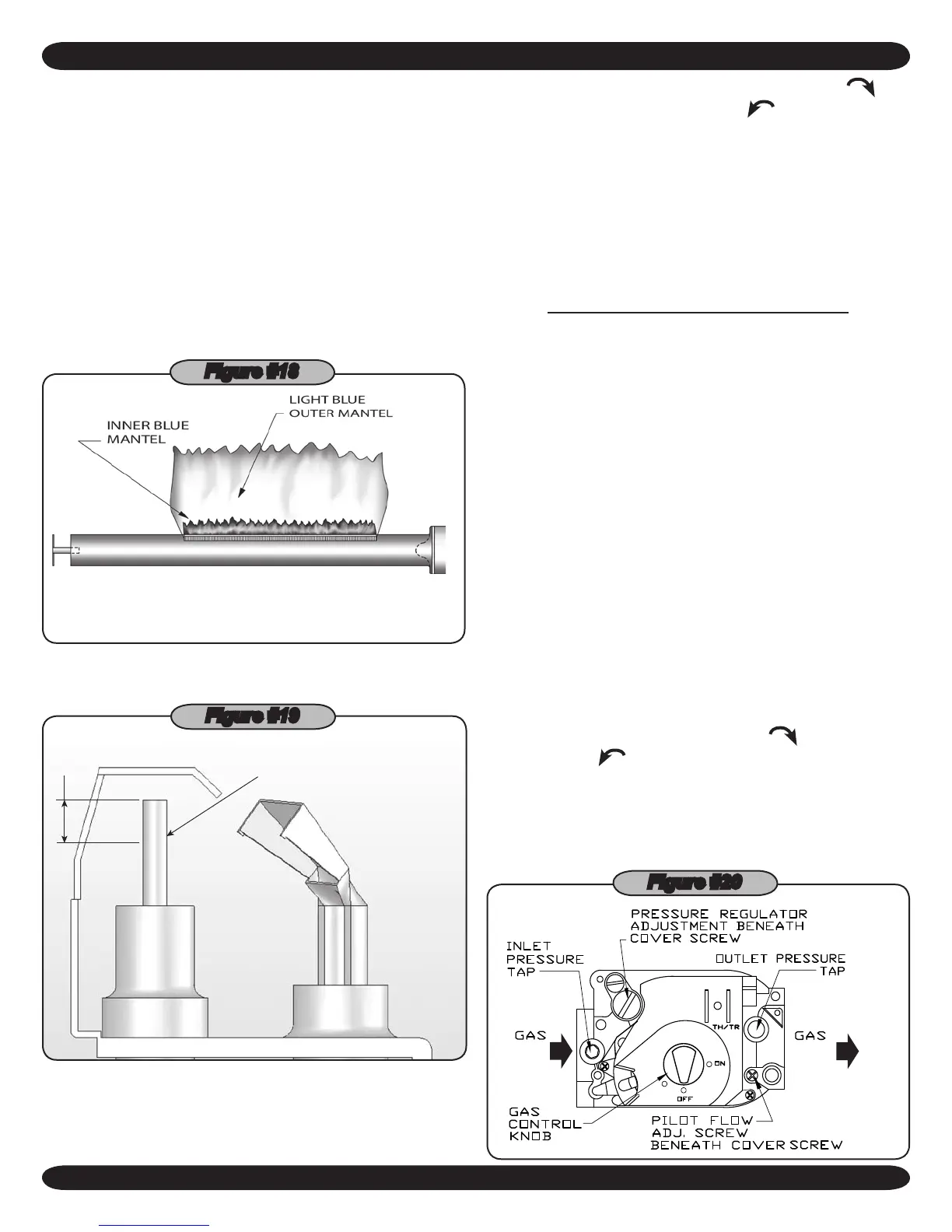
The main burner ame should form a
sharp blue inner mantel with no yellow.
opening twice per year. DO NOT OVER OIL. Follow the
manufacturers instructions attached to the circulator.
When oil cups or holes are not provided, bearings are
either permanently lubricated or water lubricated.
Visually check the main burners and pilot ame at the
12.
start of each heating season and again midway through
the season.
Check the burner throats and burner orices for lint and A.
dust obstructions. See
gure #17
.
The main burner ame should have a well dened in-B.
ner blue mantel with a lighter blue outer mantel. See
gure #18
.
Figure #18
The pilot ame should envelop ⅜ to ½ inch of the tip of C.
the pilot sensing device. See
gure #19
.
IGNITION ELECTRODE
3/8” TO 1/2”
IN FLAME
Figure #19
Adjusting the pilot ame:
13.
Remove the pilot adjustment cover screw.A.
GENERAL INSTRUCTION FOR SEASONAL START UP AND MAINTENANCE
Turn inner screw (adjustment screw) clockwiseB. to
decrease and counterclockwise to increase the
pilot ame, see gure #20.
After adjustment, be sure to replace cover screw to C.
prevent possible gas leakage.
The main burners and the pilot burner should be D.
checked for signs of corrosion or scale build up.
Clean main burners and pilot burner with a steel bristle E.
brush.
CHECK GAS INPUT RATE TO BOILER
Maximum permissible gas supply pressure must not be
1.
higher and minimum supply pressure must not be lower
than what is specied on the rating plate.
To check for proper ow of natural gas to boiler using the
2.
gas meter, proceed as follows:
Turn off the gas supply to all other appliances, except A.
the boiler.
With the boiler operating, determine the ow of gas B.
through the meter for two minutes and multiply by 30 to
get the hourly rate (in cubic feet).
Divide the input rate shown on the rating plate by the C.
heating value of the gas as obtained from the local gas
company. This will determine the number of cubic feet
of gas required per hour.
If minor adjustment is necessary, adjust the pressure D.
regulator on the combination gas control. Increase or
decrease manifold pressure to obtain gas input required
as described on the rating plate. To increase, turn the
regulator adjusting screw clockwise
or counter-
clockwise
to decrease pressure, see Figure #20.
The manifold pressures are taken at the outlet side of
the gas valve.
Relight all the other appliances turned off in step "a." E.
above. Be sure all pilot burners are operating.
Figure #20