10
B-01286 USLR-XLT Maintenance (11-25-19)
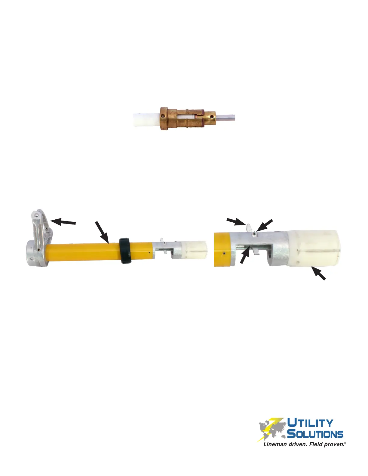
Ensure the Arc Tubes remain clean and free of oils, greases etc.
1. Use an all purpose very ne nylon mesh sanding pad to remove surface soot deposits
on the XLT Internal Female Contact (C-00517).
2. Inspect the XLT Internal Female Contact (C-00517) for signs of excessive pitting
or damage. Pay particular attention to the tips of the “ngers” along the bi-metal
interface. Replace if necessary.
3. Resize the ngers on the XLT Internal Female Contact (C-00517) around the brass /
arc ring if necessary. Each of the ngers should make light contact with the brass /
arc ring portion of the Probe Shaft Assembly (P-00049 XLT-1 or P-00449 XLT-2).
4. Inspect the Yellow Tube Assembly (XLT-1 P-00048, XLT-2 P-00447). The assembly
comes complete from the factory and should not be rebuilt. Replace as necessary
based on these conditions:
The assembly must remain clean and free of oils, greases etc..
a) Ensure the berglass is not damaged or discolored.
b) Inspect both ends of the Load Break Trigger for signs of excessive wear.
c) Verify the Load Break Trigger Torsional Spring operates correctly.
d) Verify the Pin Plug is rmly fastened. It should not be loose, and should be seated
slightly recessed in the housing. If necessary re-tighten and apply Loctite 263.
e) Ensure the white plastic XLT Gasket Tube (C-00504) is not damaged; particularly
where the Reset Button engages.
f) Inspect the XLT Hook Loop Assembly for signs of excessive pitting or damage. It
should pivot smoothly with positive spring pressure.
5. Wax the berglass portion of the assembly using Load Break Tool Fiberglass Cleaner
/ Wax (B-00159).
Yellow Tube & Components Inspection and Cleaning
a
b
c
d
e
f
 Loading...