13
B-01286 USLR-XLT Maintenance (11-25-19)
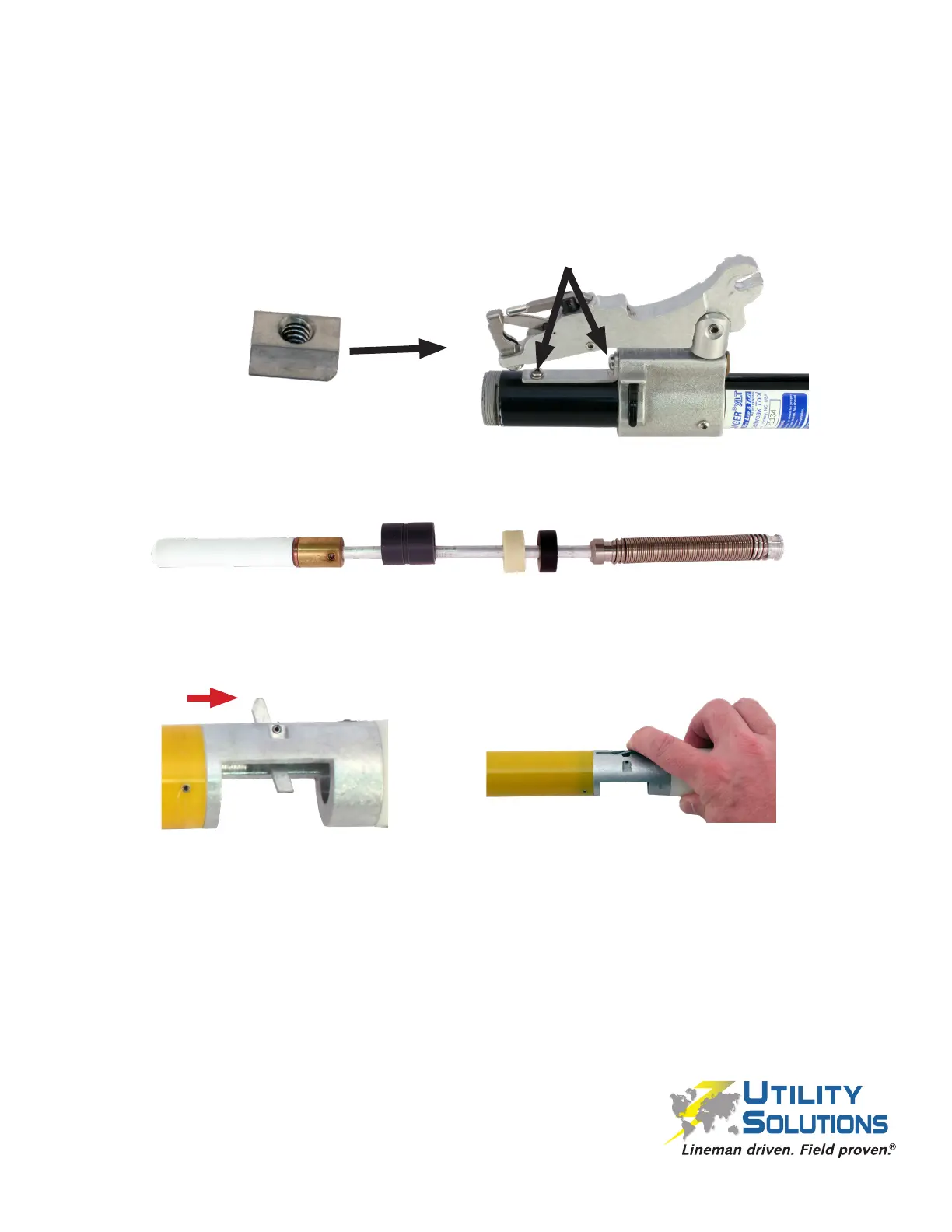
1. Install a XLT Stop Bar (C-00507) with the beveled edge facing toward the Can/Arm
Assembly then set the Short Conductor Path (C-00519) in place.
2. Attach the Short Conductor Path (C-00519) to the XLT Stop Bar (C-00507) using a
10-24 x 5/16” PHMS (B-00577) and a #10 SS Flat Washer (B-00042) with Loctite
263 (B-01073). Attach the other end of the Short Conductor Path (C-00519) to the
Can Assembly using a 1⁄4”-20 x 3/8” PHMS (B-00555) with Loctite 263 (B-01073).
3. Orient the XLT Lifesaver (C- 00532), XLT Bumper (C-00531), and XLT Spacer on the
Probe Shaft Assembly as shown.
4. Hold down the Trigger on the Yellow Tube Assembly (XLT-1 P-00048, XLT-2 P-00447)
towards the white polymer end compressing the srping. The Trigger should be under
tension and t completely inside the channel on the aluminum body.
5. Slide the Probe Shaft Assembly (P-00049 XLT-1 or P-00449 XLT-2) into the Yellow
Tube Assembly (XLT-1 P-00048, XLT-2 P-00447) completely until it stops. The Coil
Pack Assembly will extend beyond the Tube.
Reassembly Procedure
Beveled edge facing Arm
Assembly
 Loading...