11
B-01286 USLR-XLT Maintenance (11-25-19)
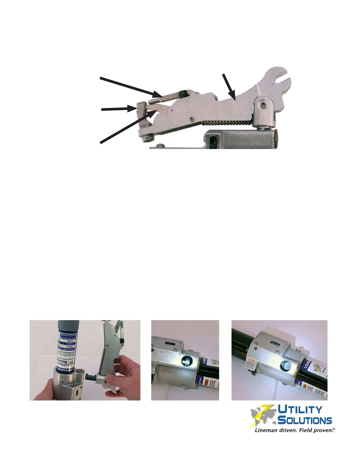
1. Inspect the Overhead Arm Assembly (P-00052) for damage and proper movement.
The assembly should smoothly swing 30 degrees from center in both directions and
return to center when released.
2. Ensure the Clip Flipper (C-00598) pivots smoothly up and down and does not rub
against the slot on the XLT Clip Post (C-00597).
3. Ensure the Clip Assembly (P-00031) pivots smoothly 45 degrees side to side and
returns to center when released.
4. Clean with warm soapy water if necessary.
Note: Follow instructions below to remove and install the Overhead Arm Assembly
(P-00052) if needed.
Remove
1. Remove the 1/4”-20 x 7/8” Cup Point SHSS (B-01268) inside the Can to allow the
Overhead Arm Assembly (P-00052) to swivel 180 degrees using a 1/8” Allen Wrench.
2. Position the Overhead Arm Assembly 180 degrees from its original position with the
Black Tube upside down. Remove the Overhead Arm Assembly.
Reassemble
1. Re-install the Overhead Arm Assembly (P-00052) in the correct orientation (spline
end down). Insure the hole in the Can Assembly is not blocked by the Pressure Pin.
Push the Pressure Pin back inside the hole if necessary.
X
Overhead Arm Assembly Inspection and Cleaning
Clip Flipper
(C-00598)
XLT Clip Post
(C-00597)
Clip Assembly
(P-00031)
Overhead Arm Assembly
(P-00052)
 Loading...