7
B-01286 USLR-XLT Maintenance (11-25-19)
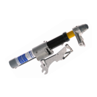
1. Using a #2 Phillips Screwdriver remove the two 10-24 x 1/2” Fillister Head Machine
Screw w/ Patch (B-01072) that fasten the XLT Mufer Assembly (P-00044) to the
Yellow Tube Assembly (P-00048 XLT-1 or P-00447 XLT-2).
2. Remove the XLT Mufer Assembly (P-00044), XLT Female Contact (C-00517), and
the XLT Arc Shim (C-00509).
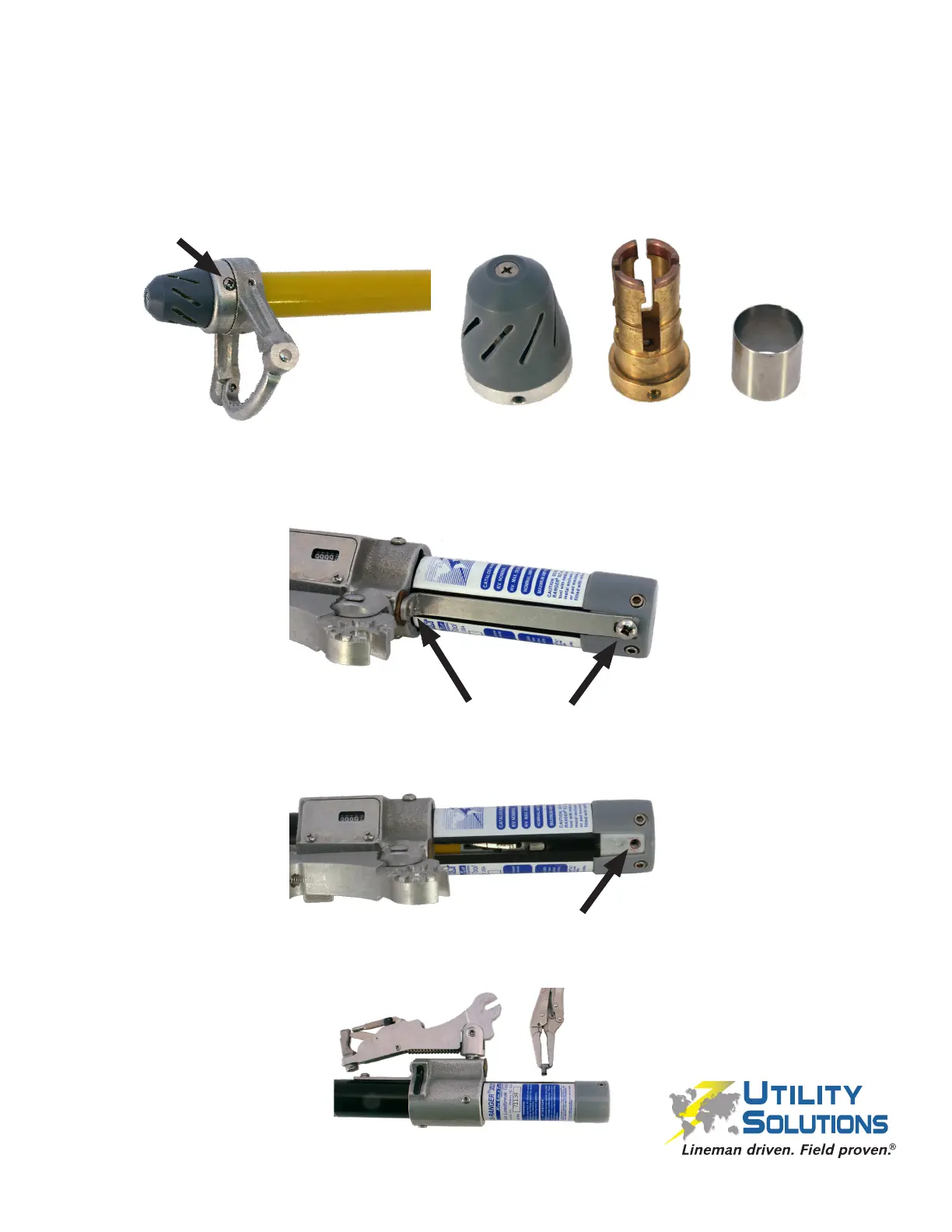
3. Using a #2 Phillips Screwdriver, remove the Long Conductor Path (C-00520 XLT-1 or
C-00541 XLT-2) by unfastening the 10-24 x 5/16” PHMS (B-00577) and the 1⁄4”-20
x 3/8” PHMS (B-00555).
4. Remove the 1⁄4”-20 x 1⁄4” Cup Point SHSS w/ patch (B-00021) that fastens the Probe
Shaft Assembly (P-00049 XLT-1 or P-00449 XLT-2) to the Black Tube Assembly
utilizing a 1/8” Allen Wrench.
5. Use a 6LN Needle Nose Vise Grip to remove the Guide Pin (C-00497). Ensure any
remnants from the Slit “O” Ring (C-01080) are also removed.
Disassembly Procedure
 Loading...