8
B-01286 USLR-XLT Maintenance (11-25-19)
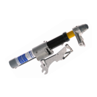
6. Unscrew the Black External Gasket (C-00513) and remove the combined Yellow
Tube & Probe Shaft Assemblies. The use of a Channel Lock Pliers may be necessary
to unthread the Black External Gasket (C-00513). It may require tapping the sides of
the Black External Gasket to loosen the threadlocker prior to unthreading.
7. Grasp the White Probe Assembly and pull on it to remove the Probe Shaft Assembly
(XLT-1 P-00049, XLT-2 P-00449) from the Yellow Tube Assembly (XLT-1 P-00048,
XLT-2 P-00447).
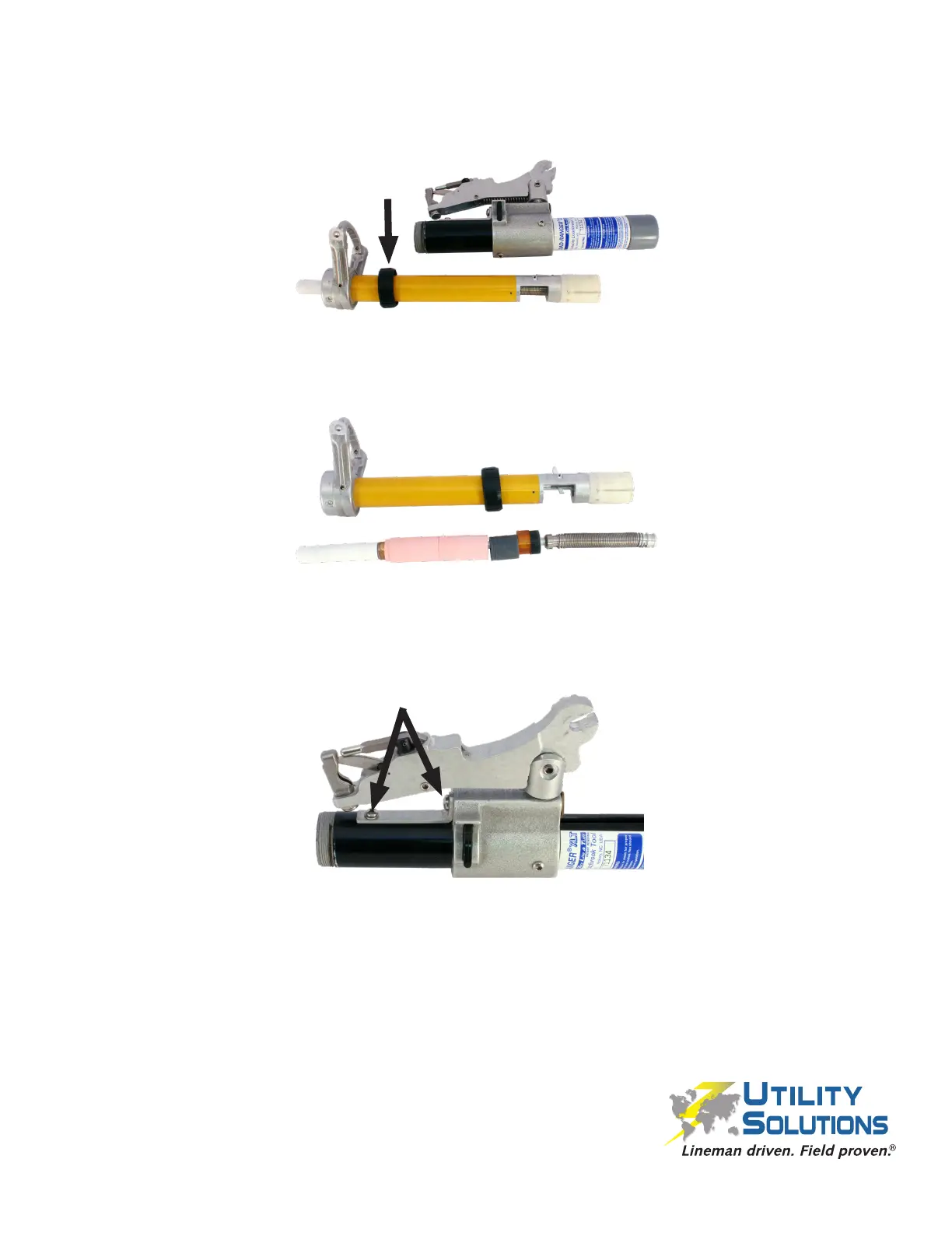
8. Using a #2 Phillips Screwdriver remove the 10-24 x 5/16” PHMS (B-00577), #10
SS Flat Washer (B-00042) and 1⁄4”-20 x 3/8” PHMS (B-00555) that fasten the Short
Conductor Path (C-00519) to the tool. Remove the Short Conductor Path (C-00519),
and the XLT Stop Bar (C-00507). The XLT Stop Bar (C-00507) is located inside the
Black Tube Assembly.
 Loading...