14
B-01286 USLR-XLT Maintenance (11-25-19)
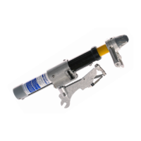
6. Insert the Pink Arc Snuffers (C-00554) into the Yellow Tube assembly, pushing them
down until they stop. Two Snuffers for the XLT-1 and four snuffers for the XLT-2.
7. Reinsert the Yellow Tube / Probe Shaft Assembly within the tool. Thread the Black
External Gasket (C-00513) onto the Black Tube Assembly.
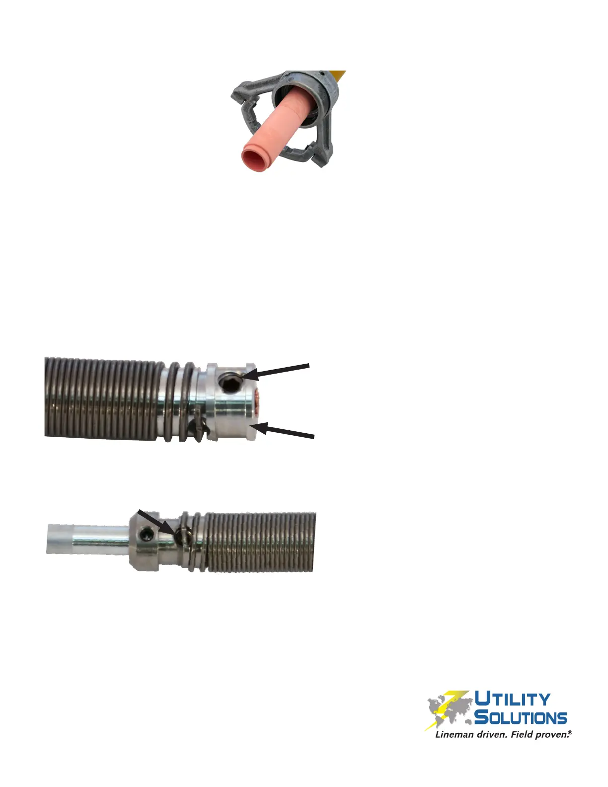
8. Rotate and push the Probe Shaft Assembly until it seats within the base of the Black
Tube Assembly. Fasten the Probe Shaft Assembly to the Black Tube Assembly using
a new 1⁄4-20 x 1⁄4 Cup Point Set Screw w/ Patch (B-00021) with a 1/8” Allen Wrench.
Do not fasten the 1⁄4“-20 Set Screw
(B-00021) into the threaded hole.
Do not fasten the 1⁄4-20 Set Screw
(B-00021) onto ledge.
Also of critical importance is the need to rotate the Coil Pack Assembly so
the Yellow Tube Trigger (C-00481) will not travel over the set screw on the
opposite coil pack end.
Ensure the Trigger Foot will not travel
over this set screw.
NOTE: A helpful hint is to look through the tapped hole for the 1⁄4”-20 x 1⁄4” SHSS
fastener and align the “witness mark” where the coil pack had previously been
fastened. This only works if the coil pack hasn’t been replaced.
 Loading...