15
B-01286 USLR-XLT Maintenance (11-25-19)
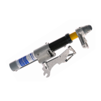
9. Attach a new Slit “O” Ring (C-01080) around the XLT Guide Pin (C-00497), apply a
small amount of Contact Grease (B-01274) to the portion of the Guide Pin (C-01080)
that is pressed into the Yellow Tube Assembly. Use a 6LN Needle Nose Vise Grip to
install the assembly into the Yellow Tube Assembly. Note the orientation of the XLT
Guide Pin (C-00497).
10. Insert the XLT Arc Shim (C-00509) followed by the XLT Female Contact (C-00517)
then fasten the XLT Mufer Cap Assembly (P-00044) using two new 10-24 x 1⁄2”
Fillister Head Machine Screw w/ Patch (B-01072).
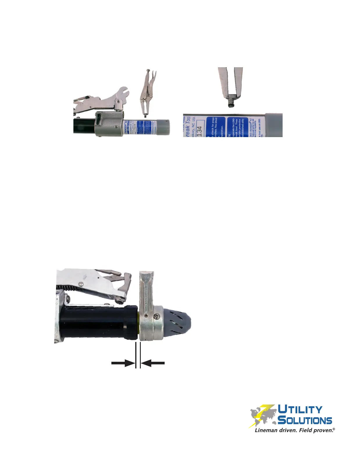
11. Verify the Reset Gap Distance is at least 0.050” by operating the tool to determine
the reset point (you should see a little of the yellow tube after the trigger resets on the
return stroke). If the trigger gap distance is not correct the Probe Shaft Assembly will
need to be adjusted by moving the location that the 1⁄4”-20 x 1⁄4” SHSS (B-00021)
engages the bottom end of the coil pack assembly.
12. Once gap distance is correct, reattach the Long Conductor Path (C-00520 for the
XLT-1 or C-00541 for the XLT-2 unit) to the Black Tube Assembly using a 10-24
x 5/16” PHMS (B-00577) and a 1⁄4”-20 x 3/8” PHMS (B-00555) with Loctite 263
(B-01073).
The trigger must reset
before the yellow tube
assembly fully retracts.
0.050” GAP
 Loading...