25
3V3
It is 3.3V voltage on board that powers the micro controller and the RTC.
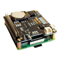
LED
It is connected to the anode of the white LED. You can use this pin to connect your own LED, but
don’t forget to put a 1K resistor in serial.
ALARM
It is the interrupt signal that generated by the RTC alarm. It is in 3.3V level and has HIGH state
(3.3V) by default. If any alarm occurs (scheduled startup or shutdown), it goes to LOW state (0V),
and this state will be cleared once Witty Pi 3’s software detects and processes it.
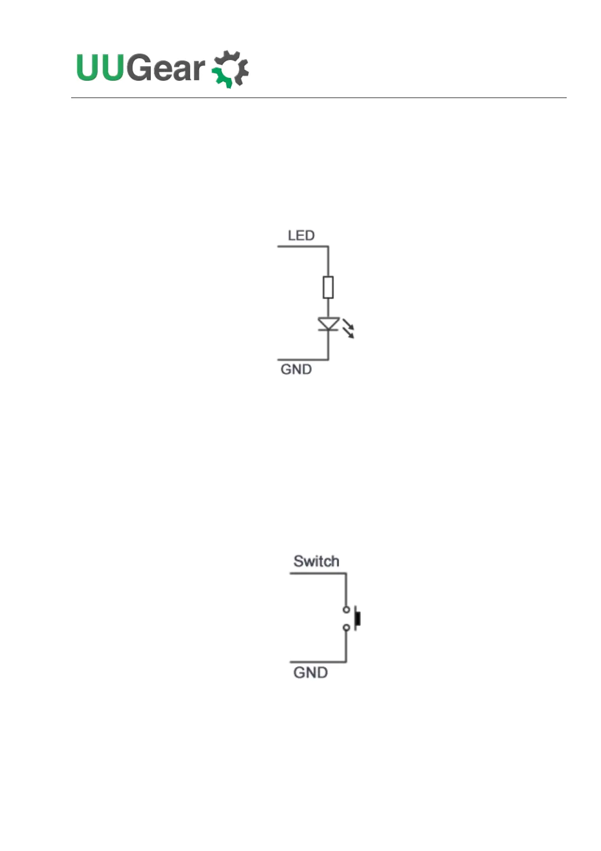
SWITCH
It is the signal line that connects to the switch (button) on Witty Pi 3. If you want to connect your
own (2-lead) switch, just wire the two leads to Switch and GND pins.
Alternatively, if you wish to trigger Witty Pi 3 with external signal, you can use a N-channel
MOSFET to achieve this:
 Loading...