24
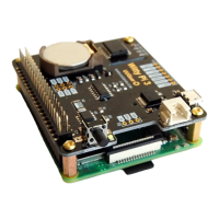
The Unpopulated 3-Pin Header (P2)
On the right edge of Witty Pi 3 board, there is an unpopulated 3-pin header, and you can decide to
use male or female header here.
This header is for inputting voltage to power Witty Pi 3. It will be useful if you neither want to input
5V via the micro USB connector, nor input higher voltage via the XH2.54 connector.
You can either input 5V between the “5V” and GND pins, or input higher voltage between the
“VIN” and “GND” pins.
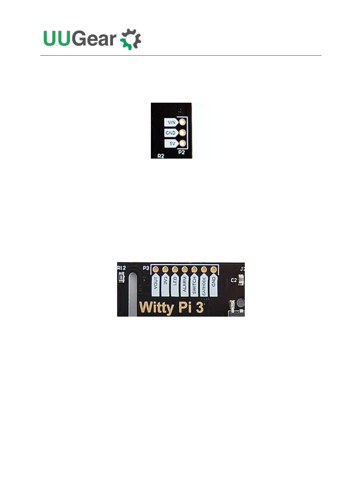
The Unpopulated 7-Pin Header (P3)
On the upper edge of Witty Pi 3 board, there is an unpopulated 7-pin header, and you can decide to
use male or female header here.
This header breaks out some useful signals and is very helpful for extension and integration. The pins
from left to right (at top view) are VOUT, 3V3, LED, ALARM, SWITCH, CATHODE and GND.
VOUT
This pin is actually connected to the +5V pin on Raspberry Pi, which is the output voltage of Witty
Pi 3 board. By detecting its voltage, you will know if your Raspberry Pi is in ON state.
Please mind the actual voltage applied to your Raspberry Pi is between VOUT and CATHODE. The
GND in this header is for Witty Pi 3, not for Raspberry Pi.
If there is another device need to get powered (by 5V) with Raspberry Pi together, you can connect it
to this VOUT and CATHODE pins.